
Mini AV Test Box Circuit

The Mini AV Test Box circuit is structured to facilitate various testing functionalities through its modular design. The 7805 voltage regulator serves as the heart of the power management system, ensuring that the microcontroller and other peripherals receive a consistent voltage level, which is critical for reliable operation. The input voltage is filtered by the 47µF capacitors to eliminate any high-frequency noise that could affect performance.
The VGA output section leverages the capabilities of the 16F84A microcontroller, which is programmed to generate the appropriate timing and signal levels necessary for VGA standards. This automatic generation of signals upon power-up simplifies the user experience, allowing for immediate functionality without additional setup.
The inclusion of a 6-pin header for programming and debugging purposes adds versatility to the design. This feature allows developers to upload new firmware or troubleshoot issues directly on the test box, enhancing its usability in development environments.
In the audio generation section, the 555 timer is configured in astable mode, producing a continuous square wave output that can be varied in frequency by adjusting the 100k trimpot. This feature enables the generation of a wide range of audio tones, making the Mini AV Test Box suitable for various testing applications, such as audio signal integrity checks and frequency response evaluations.
Overall, the Mini AV Test Box circuit is a compact and efficient solution for testing audio and video signals, making it an essential tool for electronics engineers and developers. Its straightforward design, combined with the flexibility of its components, allows for easy integration into various projects and applications.The Mini AV Test Box circuit is as simple and straight forward as I could design. It has three main sections that I split up in the schematic. The main devices used in the circuit are the 7805 +5v Regulator, 16F84A Microcontroller and 555 Timer. This is a very standard small scale power circuit that uses a 7805 to regulate the +9v input down to +5v. There are 47uF DC filtering capacitors on the input and output signals to/from the 7805. These help to keep the voltage level stable which the other digital devices in the circuit want to see. The first portion of functional circuitry is for creating the VGA output signals. The PIC does that automatically on power-up. A second set of connections are made to a 6-pin header which can be used for both programming and debugging the PIC if necessary.
This additional programming circuitry isn`t necessary if you don`t have to program your PIC `on-board`. This last portion of the schematic is where the Audio signal will be generated. The 555 timer is setup so that it will output tones from 70 Hz upto ear-piercing 14000 Hz, when the 100k trimpot is varied.
🔗 External reference
Related Circuits
Touch the sensor of the alarm with your finger, and it starts beeping. It continues for a period and then stops. Touching it again will activate the beeping once more. This description outlines a basic touch-activated alarm system. The...
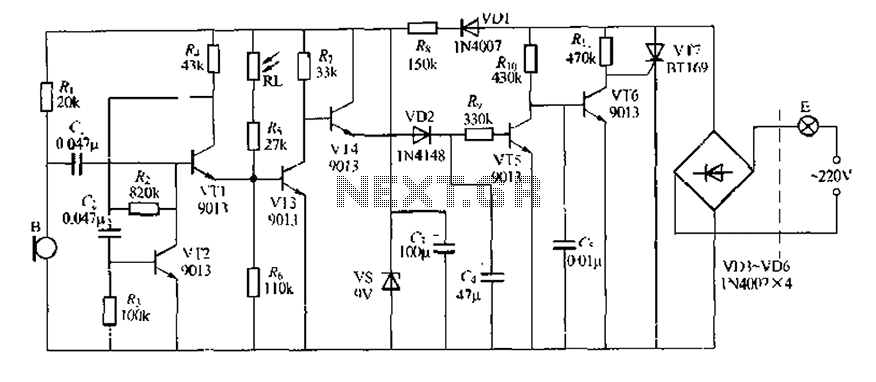
This circuit design is a sound and light control delay switch for staircase walkway lighting, featuring high voice sensitivity. In the evening, when someone walks on the stairs, their footsteps activate the electronic meter, turning on the lights. If...
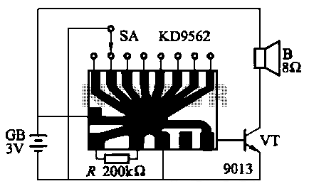
The KD9562 music octave circuit is an analog sound circuit capable of producing various sound effects including rifle shots, space shots, game console sounds, dual-tone doorbells, bomb explosions, machine gunfire, and ambulance sirens. The main electrical parameters are as...
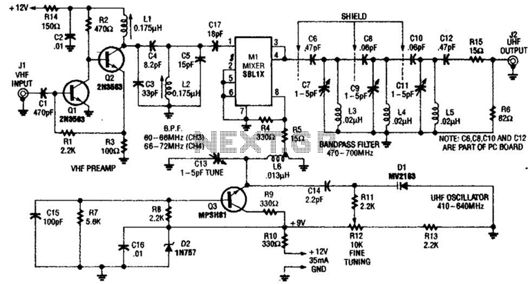
An NE592 or LM733 is utilized as a general-purpose video amplifier in this schematic. J2 and J3 deliver two anti-phase outputs. R2 functions as a gain control. The bandwidth is approximately 100 MHz. The NE592 and LM733 are operational amplifiers...
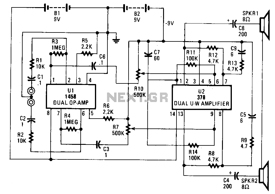
This circuit is constructed using two integrated circuits: the MC1458 dual operational amplifier, configured as a preamplifier, and the LM378 dual 4-watt amplifier. The gain of the preamplifier is determined by the resistor ratios R3/R1 for one channel and...
Figure 7-2 illustrates the FSK (Frequency Shift Keying) signal demodulation circuit, which is built using a digital phase-locked loop. This circuit features two oscillators operating at distinct frequencies: crystal oscillator X with a frequency of 983.04 kHz and crystal...