
pmw driver circuit class d amp
A PWM (Pulse Width Modulation) speed controller is a crucial component in various electronic applications, particularly in motor control systems. This type of controller allows for precise speed adjustments by varying the duty cycle of the PWM signal, which effectively controls the amount of power delivered to the motor. The setup described utilizes a Basic Stamp microcontroller, which is equipped with built-in PWM capabilities, making it an excellent tool for educational purposes and experimentation.
The circuit configuration includes a capacitor timer circuit that works in conjunction with a potentiometer (pot). The potentiometer acts as a variable resistor, allowing the user to adjust the PWM signal's duty cycle. As the potentiometer is turned, the PWM signal can be increased or decreased, which directly affects the speed of the connected motor. An LED is used as a visual indicator to demonstrate the changes in PWM output, providing immediate feedback on the adjustments made.
To amplify the PWM signal for practical use, an amplifier circuit is necessary. This circuit will take the low-power PWM output from the microcontroller and increase it to a level sufficient to drive a motor or other load. The next step in this project involves integrating a driver circuit, specifically a FET (Field Effect Transistor) driver, which is designed to efficiently control the MOSFETs used for switching the motor power. FET drivers are essential for ensuring that the MOSFETs switch on and off quickly and effectively, which is crucial for maintaining performance and efficiency in PWM applications.
The user is also exploring the concept of H-bridge configurations, which allow for bidirectional control of motors, including forward and reverse operations and regenerative braking. However, the focus remains on implementing a simple forward motion control using a single driver and a power MOSFET. This approach simplifies the design while still achieving the desired control over the motor speed.
In summary, the project involves using a PWM speed controller with a Basic Stamp microcontroller to create an adjustable speed control system. The next steps include amplifying the PWM signal and integrating a FET driver to control a power MOSFET, ultimately leading to effective motor control. Resources for learning about FET drivers and further circuit design can be found in electronics textbooks, online tutorials, and specialized forums focused on motor control and microcontroller applications.One of the critical components is a pwm speed controller, so that i can finely adjust my speed rather than just having an "on" mode that runs balls to the wall. That way may be fun for a little while but I value my life. lol PWM - I bought a basic stamp microcontroller a while back that came with a breadboard built into it.
This is the sort of controller that they sell to schools to learn microcontrollers and all of their functions. I have had a blast tinkering with it, and recently realized that it had a pwm function on it. so I set up a circuit using pwm that references a capacitor timer circuit controlled with a pot. So as I turn the pot, I increase or decrease the pwm. I threw a LED into the mix to see the results, and it works like a charm. Very simple, but to a newb like me, I was quite pleased with myself. When I finish my project I will buy a more permanent microcontroller that doesn`t have the bread board, but its a good starting point to see what I can do. So now I have a signal that is adjustable through a pot, now what I need is an amplifier to increase this signal to a useful output.
This is where it all gets a little hazy for me and my ignorance really shows through. I posted on another forum more specialized to E-biking and got a good response to some of my questions, however they raised more. I understand that the next stage after the pwm mcu, is a driver" circuit (an IC) called FET drivers, or gate drivers, WHAT IS THIS lol, more aptly where can I read up on this subject.
I also understand that many speed controllers use an H bridge for forwards, backwards, regen braking forwards, and regen braking backwards. This is getting way ahead of me and not really worth my investigation. I really only need forwards. Can I use just one driver, and one large power switching mosfet connected to my mcu Im new to the forum and have only had time to look through it briefly, however, Im glad to have stumbled upon it.
I am also very new to the electronics world. Though I have dabled in electronics my whole life, I have only recently begun to really study the subject. One of the critical components is a pwm speed controller, so that i can finely adjust my speed rather than just having an "on" mode that runs balls to the wall.
That way may be fun for a little while but I value my life. lol PWM - I bought a basic stamp microcontroller a while back that came with a breadboard built into it. This is the sort of controller that they sell to schools to learn microcontrollers and all of their functions.
I have had a blast tinkering with it, and recently realized that it had a pwm function on it. so I set up a circuit using pwm that references a capacitor timer circuit controlled with a pot. So as I turn the pot, I increase or decrease the pwm. I threw a LED into the mix to see the results, and it works like a charm. Very simple, but to a newb like me, I was quite pleased with myself. When I finish my project I will buy a more permanent microcontroller that doesn`t have the bread board, but its a good starting point to see what I can do. So now I have a signal that is adjustable through a pot, now what I need is an amplifier to increase this signal to a useful output.
This is where it all gets a little hazy for me and my ignorance really shows through. I posted on another forum more specialized to E-biking and got a good response to some of my questions, however they raised more. I understand that the next stage after the pwm mcu, is a driver" circuit (an IC) called FET drivers, or gate drivers, WHAT IS THIS lol, more aptly where can I read up on this subject.
I also understand that many speed controllers use an 🔗 External reference
Related Circuits
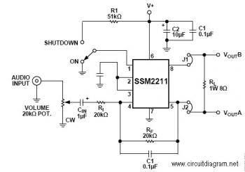
The SSM22111 is a high-performance audio amplifier that delivers 1 W RMS of low distortion audio power into a bridge-connected 8-ohm speaker load (or 1.5 W RMS into a 4-ohm load). The SSM2211 operates over a wide temperature range...
The circuit was designed to create ten different frequency bands that can be processed by a single graphic equalizer to produce and maintain a predetermined frequency response. The described circuit is a graphic equalizer that utilizes a multi-band approach to...
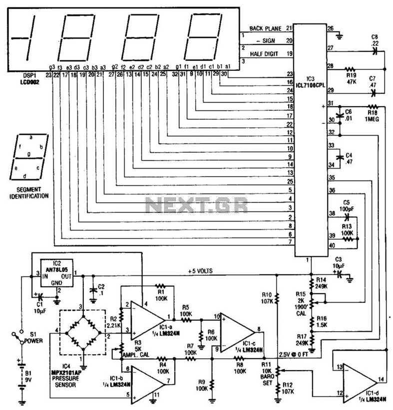
A pressure sensor (IC4) is utilized in conjunction with a DC amplifier to convert the bridge output from IC4 into a single-ended voltage. IC1 provides a reference voltage for setting the barometric pressure. IC3 is an A/D converter produced...
This circuit utilizes a 555 timer to control a 4017 decade counter. The outputs from the counter are used to drive transistor relay drivers. The duration for which the lights remain "on" can be adjusted by modifying the connections...
The transmitter described here includes an additional RF power amplifier stage following the oscillator stage, which increases the output power to 200-250 milliwatts. When connected to a properly matched 50-ohm ground plane antenna or a multi-element Yagi antenna, this...
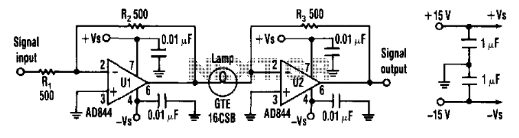
Designers can construct a 15-dB compressor using a miniature lamp and a current-feedback amplifier. The circuit exhibits extremely low distortion at frequencies above the lamp's thermal time constant, indicating that distortion remains negligible from audio frequencies to over 10...