
Electronic Roulette Game
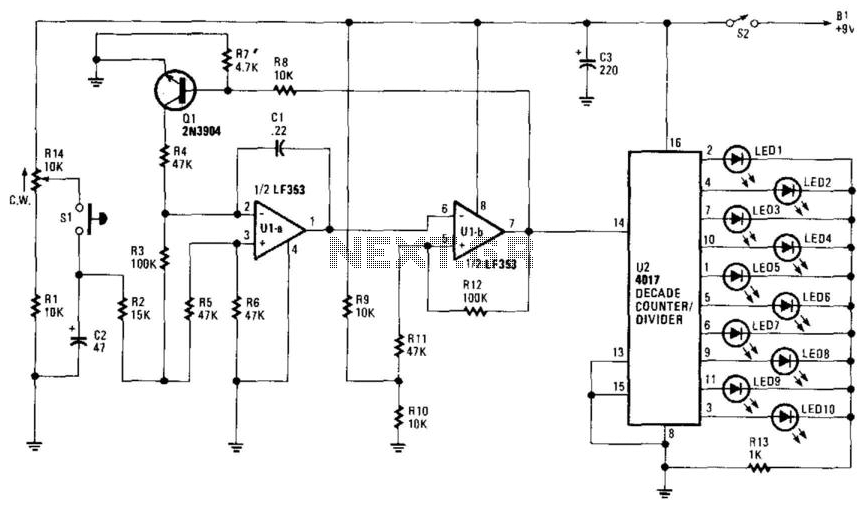
The circuit utilizes two operational amplifiers, U1A and U1B, configured as oscillators to generate a variable frequency output. The resistor R14 plays a crucial role in determining the initial frequency of oscillation by setting the charge and discharge time constants for capacitor C2. As C2 charges, the voltage across it increases, which in turn affects the feedback loop of the oscillators, leading to a gradual decrease in oscillation frequency.
The LED array, connected through resistor R10, displays the output of the oscillators. The roulette-wheel effect is achieved as the frequency of the oscillation decreases, resulting in a visual representation reminiscent of a spinning wheel. Each LED corresponds to a number, and as the oscillation slows, one specific LED will remain lit, indicating the winning number in the game.
The design can be further enhanced by incorporating a reset mechanism to allow the user to restart the oscillator sequence, as well as adjustable components to fine-tune the speed and duration of the oscillation. Additional features may include a display driver for larger LED arrays or integration with microcontrollers to introduce programmable elements into the game, enhancing user interaction and experience. R14 is set for an initial "starting" speed of the oscillator U1A and U1B. As C2 charges, oscillation begins slowin g down as C2 discharges, giving a roulette-wheel effect on LED SI through 10. The LED that remains on is the winning number. 🔗 External reference
Related Circuits
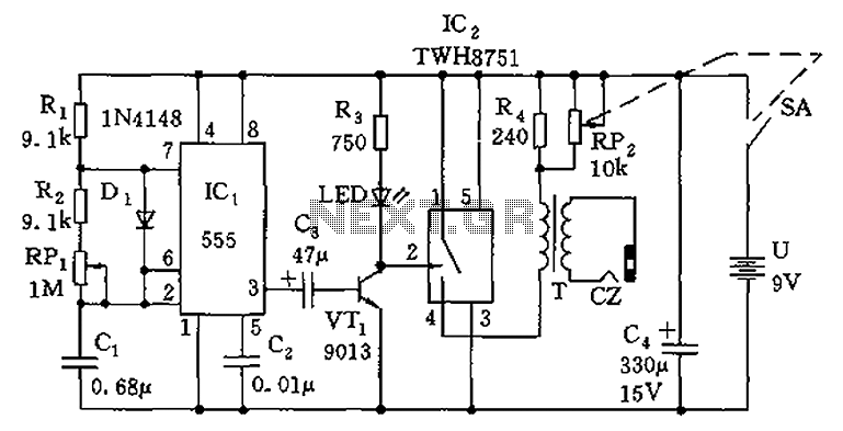
The circuit is composed of a 555 oscillator and an amplifier driver stage. It includes the 555 timer along with resistors R1, R2, RP1, capacitor C1, and other components forming a multi-harmonic oscillator. The frequency can be adjusted using...
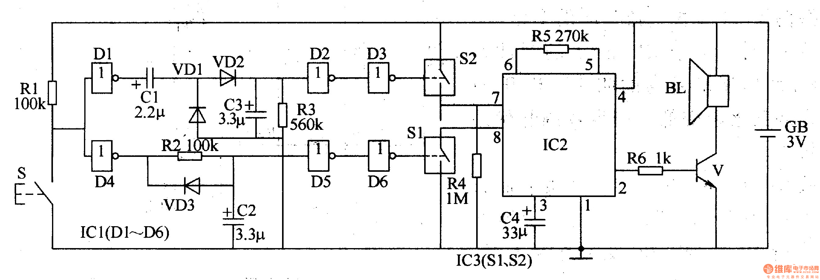
The two-tone electronic doorbell circuit comprises a trigger control circuit and a doorbell generating circuit, as illustrated in Figure 3-108. The trigger control circuit includes a doorbell button (S), resistors (R1-R3), electrical components (C1-C3), diodes (VD1-VD3), six NOT gate...
The allowable reduction in system performance. For a fire control radar, the acceptable degradation is usually expressed as a reduction in range; for example, the maximum lock-on range might be degraded by 25 percent without loss of essential defense...
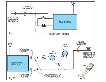
A radio-controlled electronic flash is an essential tool in any photographer's kit. Professionals frequently utilize them, such as wedding photographers. A radio-controlled electronic flash system typically consists of a transmitter and one or more receivers. The transmitter, often mounted on the...
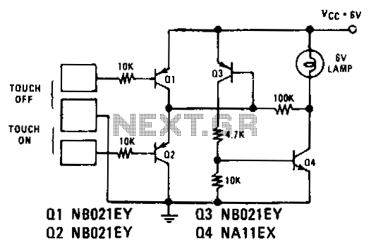
Transistors Q1 and Q2 control latches Q3 and Q4 to switch on the lamp. A high resistance from touching the electrode biases Q1 or Q2 on, setting or resetting the latch. In this circuit, transistors Q1 and Q2 function as...
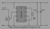
The TDA7052 is a mono output amplifier housed in an 8-pin Dual In-line Package (DIP). This device is specifically designed for use in battery-operated portable audio applications. Key features of the TDA7052 include the absence of external components, elimination...