
555 simple electronic circuit diagram massage

The circuit utilizes a 555 timer in astable mode to generate a continuous square wave output. This output is critical for applications requiring variable frequency, particularly in massage therapy devices. The resistors R1 and R2, in conjunction with the adjustable potentiometer RP1, determine the timing intervals that set the frequency of oscillation. The capacitor C1 plays a pivotal role in defining the charge and discharge cycles of the timer, further influencing the output frequency.
The output pulse from the 555 timer is typically a low-voltage signal, which is insufficient to drive the massager directly. Therefore, the signal is routed to IC2, a power amplifier that increases the signal strength. The amplified output is then used to energize a pulse transformer, T, which isolates the high-voltage side from the low-voltage control side while stepping up the voltage as necessary for the massager application.
The CZ jack serves as a connection point for the massager's metal plate electrodes, which deliver the therapeutic electrical pulses to the user. The user can feel the effects of the massage through controlled electrical stimulation, which can be adjusted in intensity using RP2. This adjustability allows for personalized treatment based on user preference and comfort levels.
The inclusion of an LED indicator provides visual feedback on the operational status of the circuit, specifically indicating that the oscillator is functioning correctly and that the output frequency is stable. The spiral switch potentiometer allows for easy adjustment of the device settings, enhancing user experience by providing intuitive control over frequency and intensity.
Overall, this circuit design represents an effective solution for creating a variable-frequency massaging device, integrating essential components to ensure functionality, user control, and safety. Circuit as shown by the 555 oscillator and amplifier driver stage composition. 555 and R1, R2, RP1, C1 and other components of a multi-harmonic oscillator whose frequency can b e adjusted by RP1, namely f 1.44/(R1 + R2 + RP1) C1. Parameters given frequency range is shown 2 ~ 106Hz. 555 low-frequency pulse output by anti VT1 adding to the input of IC2, the power amplifier driving pulse transformer T, followed by the level of CZ jack connected massager metal plate electrode, strain on the human body or parts of the massage care. LED instructs the oscillation frequency synchronization light. RP1 to adjust the frequency, RP2 adjust the massage intensity; SA adopts spiral with switch potentiometer.
Related Circuits
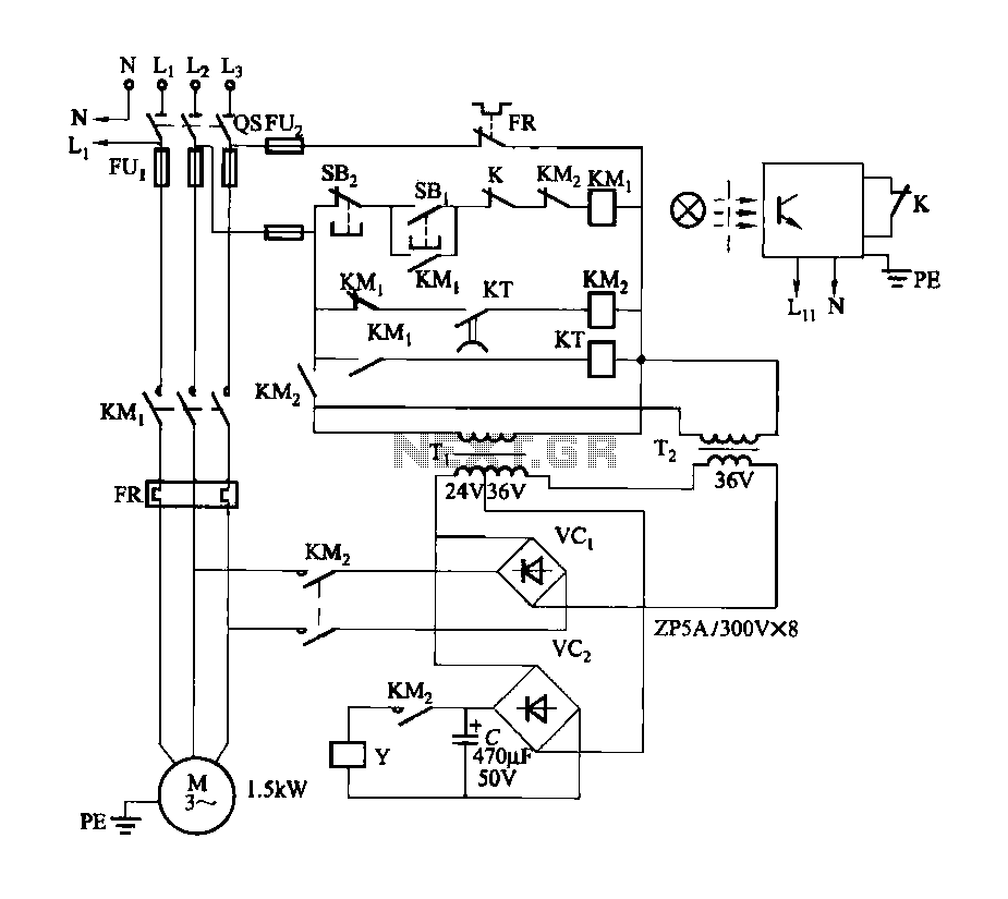
Figure 3-142 illustrates the reel control circuit. The coiler is utilized for winding plastic banding, such as grafting tape, onto a plastic reel. To prevent the plastic tape from being pulled off due to its low tensile strength, the...
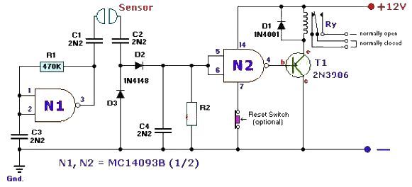
This fluid level sensor circuit is designed to use an AC sensing signal to prevent electrolytic corrosion on the probes. The rectified AC signal is utilized to drive a T1 transistor, which in turn activates a 12-volt relay that...
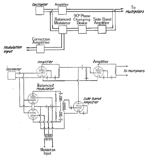
A system is being developed to transmit in the FM band. The oscillators have already been constructed to facilitate transmission across multiple frequencies. The design of an FM transmission system involves several key components, including oscillators, modulators, amplifiers, and antennas....
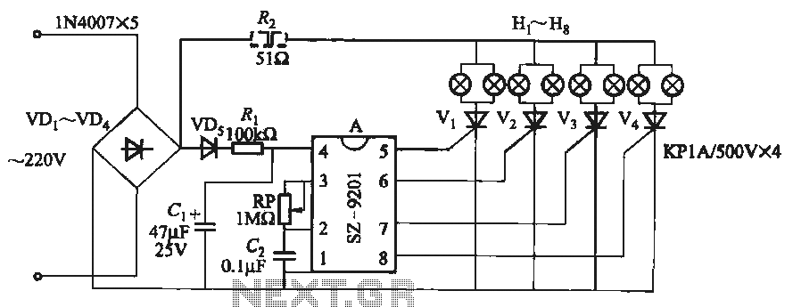
It utilizes the mains supply through a basic DC rectifier circuit. The circuit operates by converting alternating current (AC) from the mains supply into direct current (DC) using a rectifier. A typical implementation involves a bridge rectifier configuration, which consists...
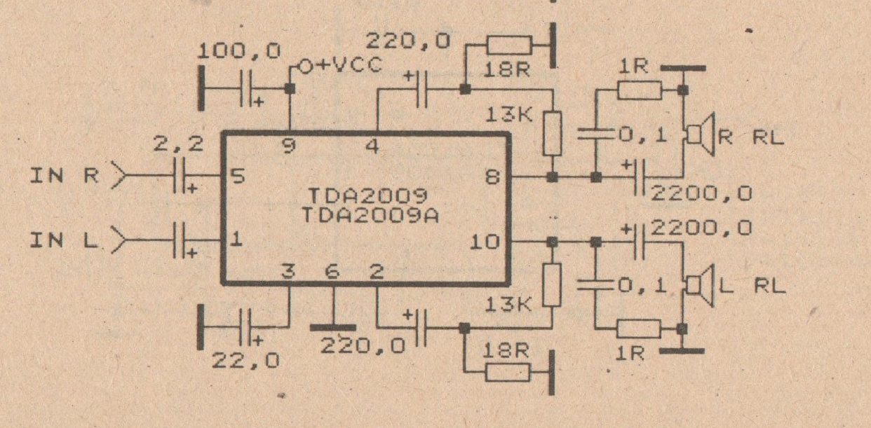
The minimum voltage required for this circuit is 8 volts, while the maximum voltage is 28 volts. It can be used to amplify audio signals in electronic devices such as radios, DVDs, MP4 players, and MP5 players. The circuit...
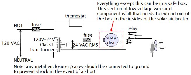
For various experiments, such as solar air heaters, an automatic fan activation and deactivation system is required. A straightforward solution is to use a bimetal snap disc thermal sensor. This sensor functions as a switch that closes when a...