
Electronic Siren based NE555
The electronic siren circuit leverages the NE555 timer in an astable mode to create a continuous square wave output, which is vital for generating the characteristic siren sound. The frequency of oscillation is primarily determined by the resistors and capacitors connected to the timer. In this design, the use of a thermistor introduces a safety feature by monitoring temperature variations. The thermistor's resistance changes with temperature, providing an input to the transistor that controls the alarm's activation. This allows the circuit to serve dual purposes: as a sound generator and a temperature-based alarm system.
The integration of the UM3561 chip enhances the circuit's capability by allowing for multiple sound effects, making it versatile for different applications. The output from the UM3561 is directed to the 2N3706 transistor, which acts as a speaker driver, amplifying the sound to a level audible to the human ear. The choice of components, including the use of a push-button switch, provides user control over the circuit, enabling activation and deactivation of the siren sound as needed.
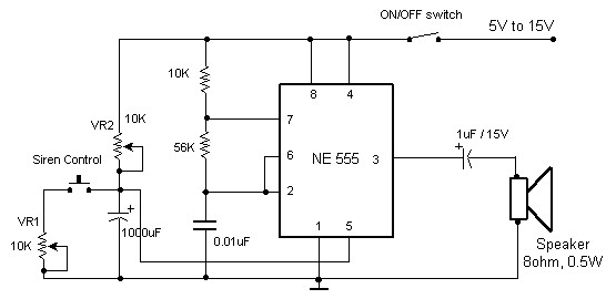
Overall, the design emphasizes simplicity and effectiveness, making it suitable for various applications, including fire alarms and security systems, where audible alerts are necessary. The ability to adjust sound frequency and utilize different sound effects further enhances the functionality of the electronic siren circuit.Here the circuit diagram of electronic siren based NE555. This circuit produces a sound like factory siren. It applies a 555 timer IC which is utilized as an astable multivibrator of a center frequency of about 300Hz. The frequency is controlled by the pin 5 of the IC. When the power supply is switched ON, . The following circuit is a simple fire alarm circuit based NE555 timer and use thermistor as a temperature detector. This sensor will activate the transistor when the temperature is in high value. The thermistor will have a low resistance at high temperature, while at low temperature, the transistor resistance is high. This characteristic of thermitor. This is the sound generator which will simulate British police car siren. The circuit is built using 2 pieces of timer IC 555 to generate sound frequency. How the circuit work: The 555 on the right is wired as an alarm sound generator and the second 555 timer on the left is a 1 Hz.
This easy electronic buzzer circuit built based on timer works for gaining the frequency. The IC timer NE 555 used as astable multivibrator operating at about 1kHz and produces a sound when switched on. The sound frequency can be adjusted by varying the 10K resistor. You may change the 10K resistor with variable resistor. This is a really simple sound effect generator based single sound generator chip UM3561. The UM3561 will generate four kinds of sound effects. The basic operation is that the UM3561 will generate the sound signal, then the signal delivered to 2N3706 (as speaker driver) to be amplified so you can hear the sound from a.
This is Electronic Siren circuit diagram. The sound produced imitates the rise and fall of an American police siren. When first switched on the 10u capacitors is discharged and both transistors are off. When the push button switch is pressed to 10u capacitor will charge via the 22k resistor. This voltage is applied to the. 🔗 External reference
Related Circuits
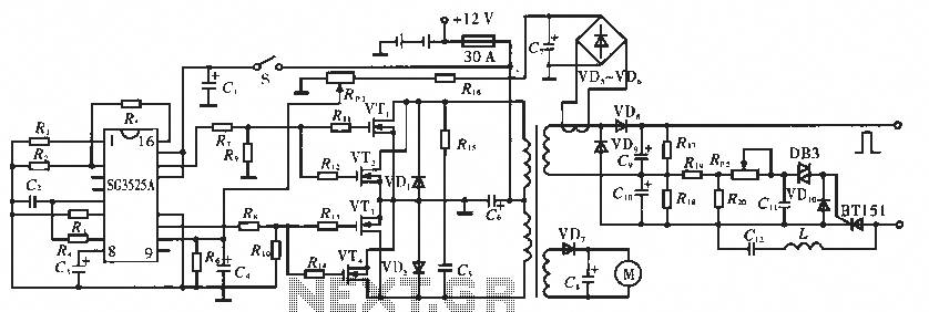
The circuit utilizes the SC3525A, a PWM silicon chip from US General Semiconductor. It features an error amplifier with an inverting input at pin 1. Pin 2 serves as the non-inverting input for the error amplifier. Pins 5 and...

A simple crystal oscillator can be constructed using a comparator from the LT1720/LT1721 series; however, this design may encounter several inherent limitations and issues. While the LT1720/LT1721 provides the correct logic output when one input falls outside the common...

The TDA7383 features a fully complementary PNP/NPN output configuration, enabling a rail-to-rail output voltage swing without the need for bootstrap capacitors. This design significantly reduces the component count, allowing for compact assemblies. An integrated clipping detector facilitates gain compression...
This is a straightforward sound effect generator based on the single sound generator chip UM3561. The UM3561 can produce four types of sound effects. Its basic operation involves generating a sound signal, which is then delivered to a 2N3706...
This circuit provides a good siren noise suitable for warding off robot-predators! Change the pitch by adjusting R2, and R5. More: all resistors are 5 or 10 percent tolerance, 1/4-watt all capacitors are 10 percent tolerance, rated 35 volts...
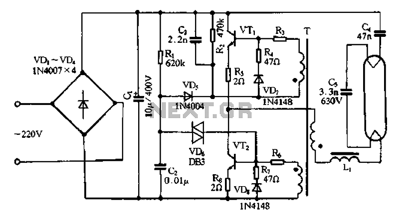
Bridge rectifier circuit in the electronic ballast application circuit The bridge rectifier circuit is a crucial component in electronic ballast applications, primarily utilized for converting alternating current (AC) to direct current (DC). This conversion is essential for powering various electronic...