
warbler siren

The circuit described is designed to generate a siren-like sound, which is effective for deterrent purposes, such as warding off robotic intruders. The primary components involved in producing the sound are resistors and capacitors, which are configured to create an oscillating signal.
The circuit likely employs a simple oscillator configuration, possibly a 555 timer IC or a similar oscillator circuit. The frequency of the oscillation, which directly affects the pitch of the siren noise, can be modified by adjusting resistors R2 and R5. These resistors are integral to setting the timing intervals of the circuit, thus allowing for a range of sound pitches. The ability to change the pitch can be useful for creating varied alert signals.
Resistors used in the circuit should have a tolerance of 5% to 10% and a power rating of 1/4 watt, ensuring reliability and stability in performance. The choice of capacitors is also critical; they should be rated for at least 35 volts and possess a tolerance of 10%. The voltage rating ensures that the capacitors can handle the potential voltage fluctuations within the circuit without failure.
In summary, this siren circuit is a straightforward yet effective design for producing audible alerts. The adjustment of R2 and R5 allows for customization of the sound output, making it versatile for different applications. Proper selection of components based on their specifications is essential for optimal circuit performance and longevity.This circuit provides a good siren noise suitable for warding off robot-predators! Change the pitch by adjusting R2, and R5. all resistors are 5 or 10 percent tolerance, 1/4-watt all capacitors are 10 percent tolerance, rated 35 volts or higher 🔗 External reference
Related Circuits
This circuit was requested by several correspondents. Its purpose was to obtain more power than the siren circuit already available on this website (One-IC two-tones Siren) and to avoid the use of ICs. A complementary transistor pair (Q2 &...
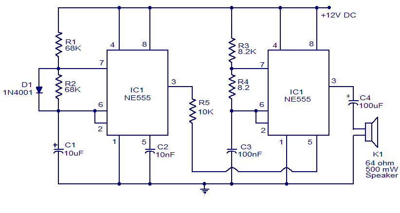
A variety of electronic circuits utilize the NE555 timer integrated circuit (IC). The circuit diagram presented illustrates a police siren based on two NE555 timer ICs, both configured as astable multivibrators. The circuit operates on a DC voltage supply...
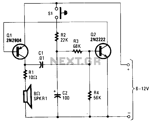
Transistors Q1 and Q2, with feedback provided via C1 from the collector of Q1 to the base of Q2, form a voltage-controlled oscillator (VCO). Depending on the voltage applied to the base of Q2, the VCO frequency ranges from...
This circuit displays a sound generator that simulates the siren of a British police car. The circuit is constructed using two timer IC 555. The sound generator circuit designed to simulate a British police car siren utilizes two 555 timer...
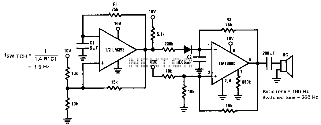
This siren provides a constant audio output while alternating between two distinct tones. The LM13080 is configured to oscillate at a fundamental frequency. This frequency can be modified by connecting a 200 kΩ charging resistor in parallel with the...
The first integrated circuit (IC) on the left is configured to operate at a frequency of approximately 1 Hz. A 47 µF capacitor is charged and discharged in a periodic manner, resulting in a gradual increase and decrease of...