
electronic thermostat and relay circuit

This thermostat circuit typically consists of a temperature sensor, a comparator, and a relay. The temperature sensor, often a thermistor or a thermocouple, monitors the ambient temperature. The output from the temperature sensor is fed into a comparator circuit, which compares the sensed temperature against a predetermined set point.
When the ambient temperature falls below the set point, the comparator activates the relay. The relay, which is an electromechanical switch, closes its contacts and allows current to flow to the space heater, turning it on. Conversely, when the temperature rises above the set point, the comparator deactivates the relay, opening the contacts and cutting off power to the heater.
It is crucial that the relay is selected based on the heater's specifications, including its voltage and current ratings. A relay with a suitable contact rating ensures safe operation and prevents potential overheating or failure. Additionally, the circuit may include a diode across the relay coil to suppress voltage spikes generated when the relay is de-energized, protecting other components in the circuit.
In summary, this simple thermostat circuit effectively manages the operation of a space heater by utilizing a relay controlled by a temperature sensor, ensuring efficient and safe heating based on the ambient temperature.Here is a simple thermostat circuit that can be used to control a relay and supply power to a small space heater through the relay contacts. The relay contacts should be rated above the current requirements for the heater.. 🔗 External reference
Related Circuits
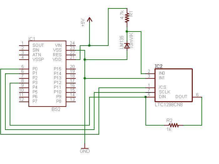
The schematic diagram illustrates the temperature sensor that is set to be launched. The LM135 sensor, functioning as a Zener diode, is connected via a foot-long cord to the circuit through a plug. This design allows the sensor to...
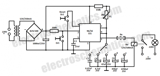
This time delay relay circuit is constructed using the NE/SE555 integrated circuit, manufactured by Intersil, which incorporates a precision timer. The circuit exhibits stability against temperature variations of 0.00. The NE/SE555 timer IC is a versatile device widely used in...
PC parallel port can be very useful I/O channel for connecting your own circuits to PC. The PC's parallel port can be used to perform some very amusing hardware interfacing experiments. The port is very easy to use when...
This circuit utilizes the MM74HC942, a single-chip low-speed modem that is compatible with the Bell 103 standard. The Bell 103 modem circuit operates at a baud rate of 300. The MM74HC942 is a versatile integrated circuit designed for low-speed data...
This circuit detects AC line currents of approximately 250mA or greater without establishing any electrical connections to the line. The current detection occurs through an inductive pickup (L1) constructed from a 1-inch diameter U-bolt wound with 800 turns of...
An active amplified transformer isolated signal splitter that enables a hum-free connection of one guitar to multiple amplifiers, while also providing a direct output. This includes a discussion on using audio transformers for equipment interconnections and mentions line-level transformers...