
circuits and programs to show how to use PC parallel port output
The PC parallel port, also known as the Centronics port, is a versatile interface that allows for bidirectional communication between the computer and external devices. Traditionally used for connecting printers, the parallel port can also facilitate various hardware interfacing experiments, making it an excellent choice for hobbyists and engineers alike.
The parallel port typically consists of a 25-pin D-sub connector, with specific pins designated for data transmission, control signals, and ground connections. The data lines (D0-D7) are used for sending 8 bits of data simultaneously, allowing for efficient data transfer. Control lines such as Strobe, Ack, and Busy are essential for managing the flow of data and ensuring that the connected device is ready to receive information.
To utilize the parallel port for custom circuits, one of the first steps involves understanding the pin configuration. For instance, pins 2 to 9 correspond to the data bits, while pin 1 is the Strobe signal, which indicates that data is ready to be read by the connected device. Properly connecting these pins to a microcontroller or other digital logic circuits can enable various applications, such as controlling LEDs, motors, or sensors.
It is also important to consider the voltage levels when interfacing with the parallel port. The standard logic levels are TTL compatible, meaning that a high signal is typically around 5V, while a low signal is close to 0V. This compatibility allows for easy integration with common microcontrollers like the Arduino or PIC series.
For effective experimentation, it is advisable to implement a simple circuit that can toggle the data pins based on user input or predefined conditions. By employing basic programming techniques, users can create a series of commands that send specific signals through the parallel port, enabling real-time interaction with the connected hardware.
In summary, the PC parallel port serves as a practical I/O channel for a variety of interfacing applications. Understanding its pin configuration and voltage levels is crucial for successful integration with custom circuits, allowing for innovative and engaging hardware projects.PC parallel port can be very useful I/O channel for connecting your own circuits to PC. The PC`s parallel port can be used to perform some very amusing hardware interfacing experiments. The port is very easy to use when you first understand some basic tricks. This document tries to show those tricks in easy to understand way. 🔗 External reference
Related Circuits
The circuit includes a momentary switch S1 that triggers an alarm pulse for the decade counter IC2, which increments its count with each alternating alarm pulse or the activation of switch S1. Ten variable resistors (VR1 through VR10) are...
While developing an infrared (IR) extender circuit, a method was needed to measure the relative intensities of different infrared light sources. This circuit utilizes an SFH2030 photodiode as the infrared sensor. A CA3140 MOSFET operational amplifier is employed in...
You can make your own 2-meter "rubber duckies" that will likely perform much better than many commercial units. I compared my design with two other "rubber duckies" of the TH215 and ICT7 which outperformed them both. With the "duckie"...
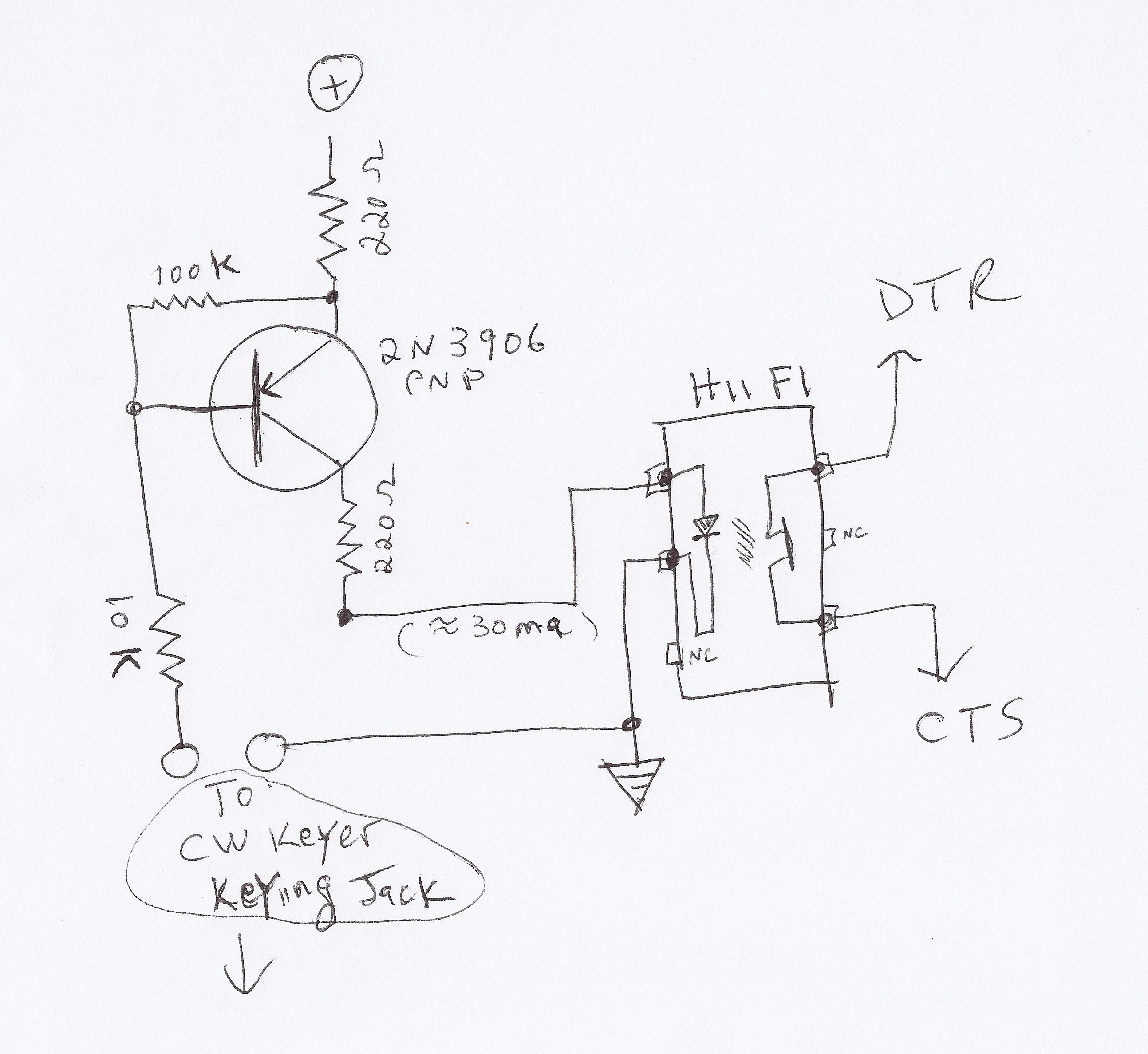
This video demonstrates how to initiate multiple instances of QsoNet's Dahdidah CW Software Keyer using FABULATECH's Virtual Serial Port Splitter. Four separate... The QsoNet Dahdidah CW Software Keyer is a sophisticated tool designed for amateur radio operators, allowing them to...
This article discusses the utilization of old PCs as simple controllers. Many obsolete systems, such as the 8088, 8086, 80286, 80386, and 80486, are no longer capable of running modern software, yet they can still function effectively. Often, individuals...
In 2011, designing a frequency converter circuit typically involves selecting an integrated circuit (IC) that meets specific requirements regarding gain and mixer spurious products, along with adding a couple of filters and a power supply. Often, the oscillator is...
Warning: include(partials/cookie-banner.php): Failed to open stream: Permission denied in /var/www/html/nextgr/view-circuit.php on line 713
Warning: include(): Failed opening 'partials/cookie-banner.php' for inclusion (include_path='.:/usr/share/php') in /var/www/html/nextgr/view-circuit.php on line 713