
Electronic Thermostat and Relay Circuit

This thermostat circuit operates by utilizing a thermistor to detect temperature variations, which are converted into a voltage signal. The LM339 voltage comparator compares this voltage against a reference voltage set by the resistors. The relay acts as a switch, controlling the power supply to the heater based on the temperature readings. The hysteresis feature prevents rapid toggling of the relay around the set temperature, providing a stable operation. The adjustment of the potentiometer allows for fine-tuning of the temperature set point, while the feedback from the thermistor ensures accuracy in temperature detection.
The choice of components is crucial; the thermistor should have a suitable resistance at the operating temperature to ensure proper voltage output to the comparator. The zener diode plays a critical role in stabilizing the voltage supply, protecting the circuit from fluctuations that could lead to erratic behavior. When designing the circuit, it is important to ensure that the relay is rated for the heater's current to prevent damage or failure. The layout of the circuit should minimize interference and ensure efficient operation, taking care to properly position the thermistor for accurate temperature sensing. Overall, this simple thermostat circuit provides an effective solution for temperature control in small heating applications.A simple thermostat circuit that can be used to control a relay and supply power to a small space heater through the relay contacts. The relay contacts should be rated above the current requirements for the heater. Temperature changes are detected by a (1. 7K @ 70F) thermistor placed in series with a 5K potentiometer which produces about 50 millivolts per degree F at the input of the LM339 voltage comparator. The two 1K resistors connected to pin 7 set the reference voltage at half the supply voltage and the hysteresis range to about 3 degrees or 150 millivolts. The hysteresis range (temperature range where the relay engages and disengages) can be adjusted with the 10K resistor between pins 1 and 7.
A higher value will narrow the range. In operation, the series resistor is adjusted so that the relay just toggles off at the desired temperature. A three degree drop in temperature should cause the relay to toggle back on and remain on until the temperature again rises to the preset level.
The relay action can be reversed so it toggles off at the lower end of the range by reversing the locations of the 5K potentiometer and thermistor. The 5. 1 volt zener diode regulates the circuit voltage so that small changes in the 12 volt supply will not effect operation.
The voltage across the thermistor should be half the supply or about 2. 6 volts when the temperature is within the 3 degree range set by the potentiometer. Most any thermistor can be used, but the resistance should be above 1K ohm at the temperature of interest. The series resistor selected should be about twice the resistance of the thermistor so the adjustment ends up near the center of the control.
🔗 External reference
Related Circuits
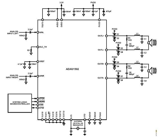
This is a stereo circuit schematic of the ADAU1592, a 2-channel, bridge-tied load (BTL) switching audio power amplifier. The ADAU1592 can be utilized in compact television sets, PC audio systems, and mini-component applications. According to the ADAU1592 datasheet, an...
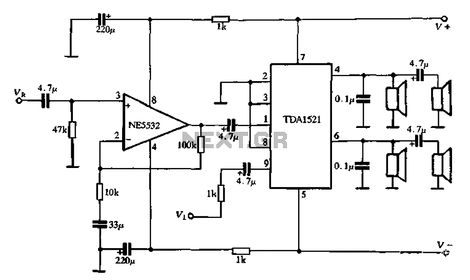
Active speaker with amplifier circuit TDA1521 and NE5532, featuring dual-channel input and dual-channel output. The active speaker circuit utilizes the TDA1521 integrated circuit, which serves as the power amplifier. This IC is designed for high-efficiency amplification, providing a robust output suitable...
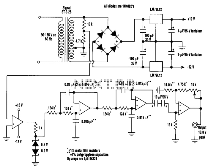
A highly stable 60-Hz sine wave can be delivered with this circuit, which offers a different and much simpler approach to achieving a stable amplitude. Capacitor coupling in the last stage removes any DC component caused by unequal Zener...
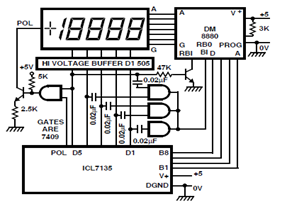
A circuit diagram for driving a plasma-type display using the ICL7135 is presented in the schematic. This application highlights the versatility of this integrated Analog to Digital Converter device. The ICL7135 is a high-precision, low-power, integrating Analog to Digital Converter...
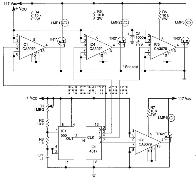
A 555 timer (IC1) controls a 4017 CMOS decade counter. The first four outputs of the 4017 drive a CA3079 zero-voltage switch. Pin 9 of the CA3079 is utilized to inhibit output from pin 4, effectively disabling the stream...

This design outlines a simple wideband output amplifier suitable for use as a 50-ohm transmission line driver. The circuit is constructed using the CA3140 operational amplifier. When utilized alongside the function generator and sine wave shaper circuits, it delivers...