
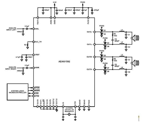
Stereo Circuit Schematic of The ADAU1592 Audio Power Amplifier
The ADAU1592 is designed to deliver high-quality audio amplification in a compact form factor, making it suitable for various consumer electronics. It operates as a bridge-tied load amplifier, which allows it to drive speakers directly without the need for a separate output transformer. This configuration enhances efficiency and reduces the overall size of the audio system.
For applications requiring a power supply voltage exceeding 15 V, the incorporation of an external protection circuit is crucial. The recommended RC snubber circuit can effectively dampen voltage spikes and transients that may occur during operation, thereby protecting the amplifier and connected components. Alternatively, a Schottky diode can be implemented to provide a fast recovery path for any reverse currents, further enhancing the reliability of the circuit.
When deploying multiple ADAU1592 amplifiers in a single audio system, careful attention must be paid to clock management. Utilizing a single clock source mitigates the risk of clock skew and the generation of unwanted frequencies that could interfere with audio quality. This approach ensures synchronized operation of the amplifiers, resulting in a cohesive audio output.
The configuration of the ADAU1592 can be tailored to specific application needs by adjusting pin settings. Setting pin 11 (MO/ST) to a high state enables a particular operational mode, allowing for flexibility in the design of the audio system. The detailed characteristics and operational guidelines for this configuration are outlined in the ADAU1592 datasheet, which serves as an essential resource for engineers and designers working with this amplifier.
Overall, the ADAU1592 is a versatile and efficient solution for audio amplification in various applications, providing designers with the tools necessary to create high-performance audio systems.This is a stereo circuit schematic of the ADAU1592, a 2-channel, bridge-tied amount (BTL) switching audio ability amplifier. You can administer ADAU1592 on collapsed console televisions, pc audio arrangement and/or mini-components applications.
According to the ADAU1592 datasheet, an alien aegis ambit is recommended to be added for applications th at crave accumulation voltage (PVDD) >15 V, you can use RC snubber or Schottky diode for this purpose. To anticipate the exhausted frequencies of asynchronous clocks (if appliance assorted ADAU1592s) in the audio band, it is recommended to use alone one alarm antecedent if the ADAU1592s allotment the aforementioned ability supply.
You can additionally body a archetypal address appliance ambit of the ADAU1592 by affairs pin 11 (MO/ST) to argumentation high, with abundant account in the datasheet. 🔗 External reference
Related Circuits
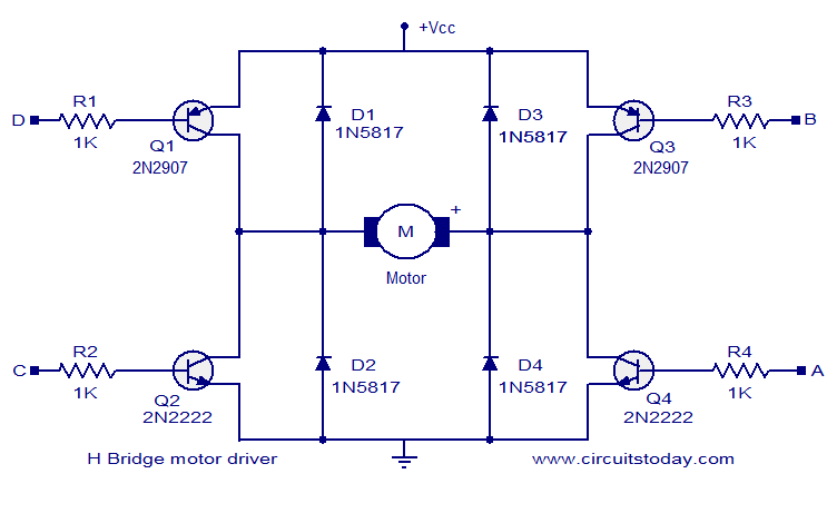
The circuit presented is a simple H-bridge motor driver circuit utilizing commonly available components. An H-bridge is an efficient method for driving motors and is widely used in various electronic projects, particularly in robotics. The circuit illustrated is a...
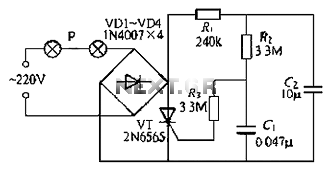
A simple and easy-to-implement one-way flashing lights string controller is designed for small shop or home decoration. This device utilizes a thyristor-based dimmer circuit, which operates effectively by managing large capacitance. The circuit includes a ten-microfarad capacitor connected to...
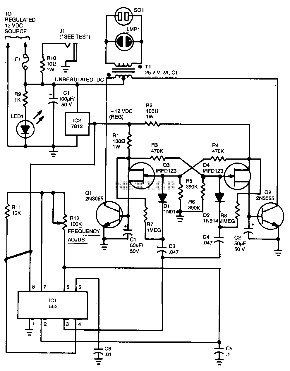
Capacitor C5 and potentiometer R12 determine the frequency of the output signal at pin 3 of IC1, the 555 oscillator. The output signal is differentiated by C3 and C4 before it is input to the base of power transistors...
The value may vary based on the switching frequency, environmental conditions, and required reliability level; therefore, it is advisable to verify this with the actual load. The maximum ambient temperature represents the highest temperature that can meet the coil...
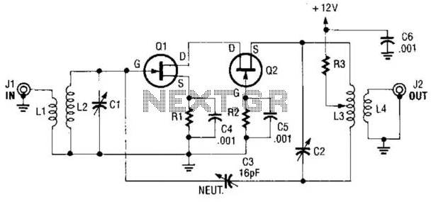
A cascode amplifier using two MOSFETs is illustrated in the diagram. L2C1 and L3C2 resonate at the operating frequency. The circuit offers advantages such as high gain, low noise figure (NF), and excellent linearity. Q1 and Q2 can be...
A homebrew 2M transceiver was designed for mobile use, eliminating the need for a fist microphone. A low-cost personal hands-free kit for mobile phones was initially considered, but it resulted in inadequate audio performance. The circuit utilized had a...
Warning: include(partials/cookie-banner.php): Failed to open stream: Permission denied in /var/www/html/nextgr/view-circuit.php on line 713
Warning: include(): Failed opening 'partials/cookie-banner.php' for inclusion (include_path='.:/usr/share/php') in /var/www/html/nextgr/view-circuit.php on line 713