
Sequential Flasher Circuit

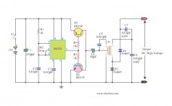
The circuit utilizes a 555 timer configured in astable mode to generate a square wave signal at a frequency of 120 Hz. This frequency is determined by the resistor and capacitor values connected to the timer. The output of the 555 timer is fed into the decade counter (4017), which counts the pulses and activates its output pins sequentially. The first four outputs of the 4017 are connected to the CA3079 zero-voltage switches, which are responsible for controlling the triacs that, in turn, manage the power to the connected lamps.
The CA3079 operates by detecting the zero crossing of the AC waveform, allowing it to switch the load on and off at a point where the voltage is nearly zero. This technique is crucial for reducing the stress on the lamps, thereby extending their operational lifespan. The inhibition feature provided by pin 9 of the CA3079 is a critical aspect of the design, as it allows for the suppression of the output pulses from the 4017 when necessary, ensuring that the triacs do not activate the lamps at inappropriate times.
Safety considerations are paramount when dealing with components connected to the AC mains. The CA3079 being directly connected to a 117-V AC power line necessitates the implementation of appropriate isolation and protective measures to prevent electrical hazards. Care should be taken during the design and assembly of the circuit to ensure compliance with safety standards and to mitigate risks associated with high voltage operation.
Overall, this circuit design highlights effective strategies for controlling AC loads with minimal interference and enhanced reliability, making it suitable for various applications where lamp control is required. A 555 timer, IC1, drives a 4017 CMOS decade counter. Each of the 4017s first four outputs drives a CA3079 zero-voltage switch. Pin 9 of the CA3079 is used to inhibit output from pin 4, thereby disabling the string of pulses that the IC normally delivers. Those pulses occur every 8.3 ms, i.e., at a rate of 120 Hz. Each pulse has a width of 120uS. Because of the action of the CA3079, the lamps connected to the triacs turn on and off near the zero crossing of the ac waveform.
Switching at that point increases lamp life by reducing an inrush of current that would happen if the lamp were turned on near the high point of the ac waveform. In addition, switching at the zero crossing reduces radio frequency interference (RFI) considerably. Caution: The CA3079s are driven directly from the 117-Vac power line, so use care. 🔗 External reference
Related Circuits
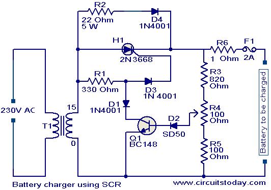
A simple battery charger based on SCR is presented. The SCR rectifies the AC mains voltage to charge the battery. When the battery connected to the charger is discharged, the battery voltage decreases, inhibiting the forward bias voltage from...

The circuit designed for distortion measurements eliminates the fundamental frequency of 1 kHz, enabling the assessment of the residual harmonic levels. Initially, a true RMS meter is employed to measure the 1-kHz input level (E^) by positioning the switch...
is circuit was requested from an email. It will allow your car headlights to flash on and off at the same time or it will cause them to flash alternately. The circuit is based on the 555 timer. It...

The circuit utilizes two main components: an integrated electronic tuner with AV output, commonly referred to as the tuner, which can receive CATV full channel TV signals and output a video signal (Vttko) along with an audio signal (Audio)....

Digital Cameras - DV machine power supply circuit. This circuit utilizes the MAX1800 chip to manage the power supply for digital cameras and DV machines. Digital cameras are typically battery-operated and require low voltages ranging from 0.7 to 5.5...
This bat detector circuit was created by Chris Eve. Initial tests with various salvaged electret microphones demonstrated a good response to frequencies of 50 kHz and higher, with smaller units performing better. Tests indicate that a small electret microphone,...
Warning: include(partials/cookie-banner.php): Failed to open stream: Permission denied in /var/www/html/nextgr/view-circuit.php on line 713
Warning: include(): Failed opening 'partials/cookie-banner.php' for inclusion (include_path='.:/usr/share/php') in /var/www/html/nextgr/view-circuit.php on line 713