
Electronic TIC TAC TOE

The project involves a microcontroller-based Tic Tac Toe game utilizing a 3x3 LED grid composed of bi-coloured LEDs. The bi-coloured LEDs allow for multiple color displays, enhancing the visual feedback provided during gameplay and in attract mode. The primary microcontroller, which may be an Arduino or similar platform, is responsible for managing the game logic, controlling the LEDs, and handling user inputs.
In attract mode, the microcontroller initiates a pre-programmed sequence that causes the LEDs to cycle through colors—specifically transitioning from red to orange to green. This sequence not only serves as an eye-catching display but also demonstrates the capabilities of the bi-coloured LEDs. The flashing pattern can be customized in terms of duration and color sequence to optimize the visual appeal.
The game logic is implemented through an algorithm that manages player turns, checks for win conditions, and updates the LED display accordingly. The 3x3 grid can be represented in the microcontroller's memory, with each LED corresponding to a cell in the Tic Tac Toe board. User inputs, likely from buttons or a touch interface, allow players to select their moves, which are then processed by the microcontroller to update the game state and the LED display.
Overall, this project serves as an educational tool, allowing users to engage with programming concepts, electronics, and algorithm development while enjoying a classic game. The combination of bi-coloured LEDs and microcontroller programming provides a platform for creativity and learning, making it suitable for both beginners and those looking to enhance their skills in electronics and software development.This project is not to introduce Tic Tac Toe. Everyone knows this game. It`s to introduce two features. Bi-coloured LEDs, microcontrollers and the skill of writing an ALGORITHM. You can use the project to learn the skills of creating the Tic Tac Toe program or create animations on the 3x3 display. When the project is turned on, the screen flashes and shows the effectiveness and capability of the bi-coloured LEDs. This is called the ATTRACT MODE and is sometimes used in amusement machines to attract players. The LEDs flash from red to orange to gree 🔗 External reference
Related Circuits

A square wave is generated by a 7555 timer operating at a supply voltage of 10V, producing an output voltage of 10V. A single quadrant multiplier (RC4200, Fairchild, obsolete) forms a two-quadrant square root circuit, converting 10V input to...
Continuous wave (CW) operation is achievable with a current of up to 350 mA from a supply voltage range of 2 to 6 V. The system supports TTL modulation frequencies of up to 10 kHz, with an adjustable duty...

Efficient automatic solar garden lights circuit with minimal components. The advantage is that it operates completely automatically, with the solar panel serving as a light detector. The efficient automatic solar garden lights circuit is designed to provide illumination using renewable...
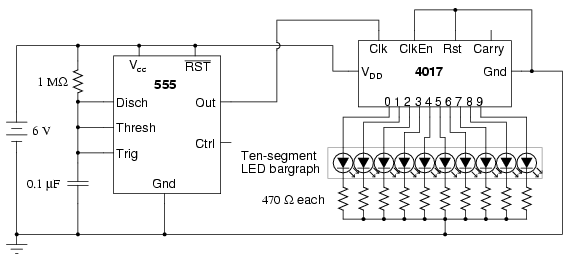
The following circuit illustrates a schematic diagram of an LED sequencer. This circuit is based on the 555 timer integrated circuit (IC). Features include a 555 timer circuit designed to debounce a mechanical switch, a 555 timer circuit to...

This circuit provides a visual 9 second delay using a 7 segment digital readout LED. When the switch is closed, the CD4010 up/down counter is preset to 9 and the 555 timer is disabled with the output held high....

Automotive engine pulse points or other sensors are filtered using the transmission device 3130 CMOS operational amplifier, which functions as a comparator to fulfill the input conditions. The pulse subsequently flows into a 4046 phase-locked loop (PLL) N-counter, which...