
Schematic Diagram Of LED Sequencer Based On The 555 Timer IC
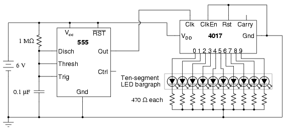
The LED sequencer circuit employs the 555 timer IC in astable mode to create a continuous pulse output. The frequency of these pulses can be adjusted by changing the resistor and capacitor values connected to the timer. The output of the 555 timer is fed into a 4017 decade counter, which counts the pulses and activates the connected LEDs in a sequential manner. Each output pin of the 4017 corresponds to a specific LED, illuminating them one after another as the timer generates pulses.
To debounce the mechanical switch, a separate 555 timer configuration is utilized. This ensures that when the switch is pressed, any bouncing effect does not cause multiple unintended pulses to be sent to the counter. The pulldown resistor is critical in this setup, ensuring that the input to the timer remains stable when the switch is not pressed, preventing false triggering.
The circuit's power supply is typically provided by a battery, ensuring portability and ease of use. The inclusion of diodes may also be present to protect against reverse polarity, ensuring that the circuit operates safely under various conditions. Capacitors are used to smooth out voltage fluctuations, providing a stable operating environment for the 555 timer and 4017 counter.
Overall, this LED sequencer circuit is an excellent example of using basic electronic components to create a visually engaging output while demonstrating fundamental principles of timing and counting in electronics.The following circuit shows about Schematic Diagram Of LED Sequencer. This circuit based on the 555Timer IC. Features: 555 timer circuit to debounce a mechanical switch, 555 timer circuit to produce clock pulses, pulldown resistor, 4017 decade counter/divider circuit for frequency division, frequency divider and timepiece (wa tch) to measure frequency, 4017 decade counter/divider circuit to produce a sequence of pulses. Component: IC, Resistor, Diode, Battery, Capacitor. [ learningelectronics. net ] 🔗 External reference
Related Circuits
This article discusses the design of an LED driver for automotive rear lights. It demonstrates that dimming is most effectively accomplished using pulse-width modulation (PWM) in conjunction with an LED driver integrated circuit (IC) that removes the requirement for...
The 555 timer is a versatile component that can be utilized as a timer and configured to produce a specific frequency. In Part II of Electronic Project I, a circuit was created to make an LED flash. This time,...
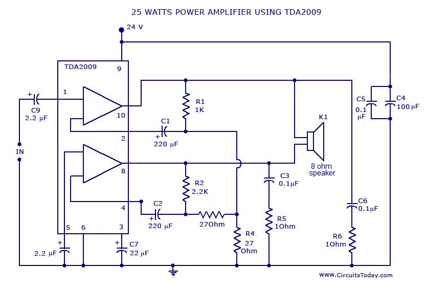
Power amplifier circuit diagram with schematics. This simple audio power amplifier circuit is designed for 25 watts output power using TDA 2009 IC, which has two channels (stereo), 12.5 W for each channel. The described power amplifier circuit utilizes the...
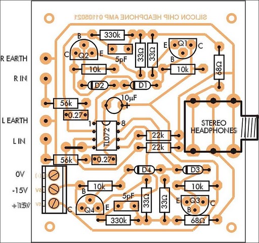
In addition to its primary function as a headphone amplifier, this circuit can be utilized for various applications requiring a wide bandwidth low-power amplifier. It is designed around an operational amplifier (op-amp), with its output current enhanced by a...
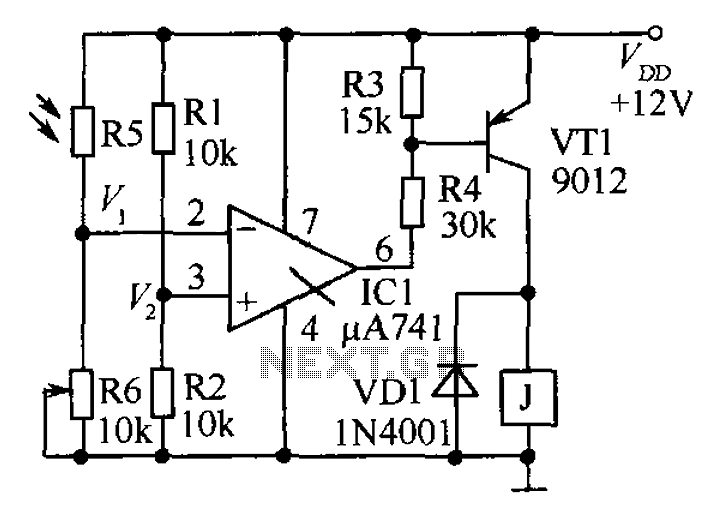
The circuit functions as a precision bright light control circuit, operating independently of power supply voltage and ambient temperature. Resistors R1, R2, R6, and the photosensitive resistor R5 form a two-arm Wheatstone bridge. The precision bright light control circuit utilizes...
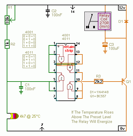
A CMOS 4001 or a CMOS 4011 can be utilized in this circuit, as both contain four two-input gates. The inputs of each gate are connected together, allowing them to function as simple inverters. This means that when both...