
Electronic Timer Switch
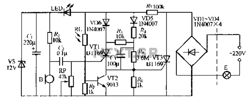
The electronic timer switch described functions as a simple ON/OFF controller for a light source, using a combination of timing circuits and a relay or transistor switch to manage the power supply to the light. The operation cycle consists of three phases: the light is activated for 100 seconds, followed by a 100-second off period, and then reactivated for another 100 seconds after a delay of one hour from the initial power-up.
The core of this timer switch can be constructed using a 555 timer IC configured in monostable mode for the short timing intervals and a microcontroller or additional 555 timer circuits to handle the one-hour delay. The 555 timer can be set up with appropriate resistor and capacitor values to achieve the desired timing durations.
For the one-hour delay, a microcontroller can be programmed to keep track of time using its internal clock, allowing for more precise control and flexibility in timing adjustments. The output from the timer circuit can drive a relay or a MOSFET to switch the light on and off, ensuring that the circuit can handle the required load without overheating.
Power supply considerations are also critical. The circuit should be powered by a reliable source, ideally a DC supply that can be converted from AC mains using a transformer and rectifier, ensuring that the voltage and current levels are appropriate for the components used.
In summary, this timer switch project is an excellent introduction to timing circuits, providing practical experience in circuit design, component selection, and programming (if a microcontroller is used). It is suitable for home automation applications, allowing for controlled lighting based on a simple timing mechanism.This electronic timer switch will ON your light for 100 seconds, OFF for another 100 seconds and ON again for 100 seconds after an hour of powering up the circuit. Good home project to build 🔗 External reference
Related Circuits
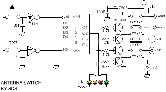
A use has been found for a collection of DIP-style RF relays acquired from a discount electronics shop. These relays are completely sealed and RF shielded, featuring low contact capacitance, making them suitable for VHF frequencies. They operate at...
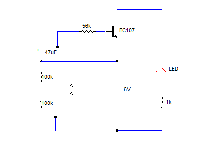
A simple transistorized one-minute delay timer circuit. It does not include any complex or critical components. This circuit can generate a time delay of approximately one minute. When the switch (preferably a push-button type) is pressed, the LED turns...
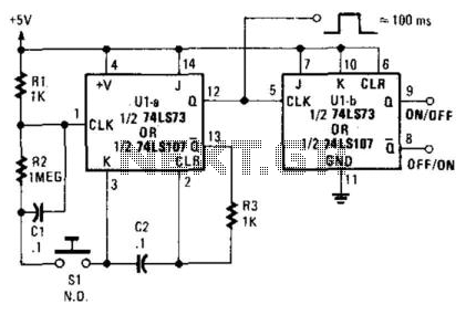
A 7473 JK flip-flop U1A is configured as a monostable multivibrator to drive U1B, functioning as a switch debouncer. The circuit features a self-clearing mechanism during power-up, providing a 100-ms pulse at pin 12 of U1A. The circuit utilizes the...
A switching power supply with an output voltage significantly lower than its input voltage exhibits an interesting characteristic: the current drawn by the supply is less than its output current. However, the input power (UI) is greater than the...
A relatively simple circuit for controlling a stair walkway light with a delay feature. The circuit has a drawback in that the voice activation is somewhat less sensitive, making it sometimes difficult to trigger with general conversation. However, it...
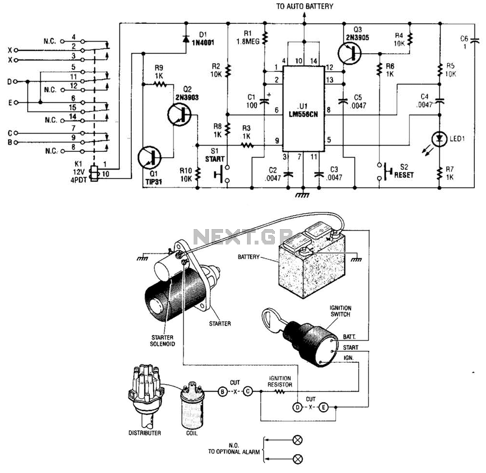
The automobile delayed kill switch operates on a straightforward principle. Upon exiting the vehicle, a hidden pushbutton switch is activated. Although no immediate effect is visible, after a preset duration, a relay engages and locks in place. This action...