
Switch Debouncer

The circuit utilizes the 7473 JK flip-flop, a dual J-K flip-flop with preset and clear functions, to create a reliable switch debouncer. In this configuration, U1A is set up in monostable mode, which means it will output a single pulse in response to a triggering event. The output pulse duration is determined by external timing components, typically a resistor and capacitor connected to the timing pins of the flip-flop.
When the circuit is powered on, a self-clearing feature ensures that any previous states are reset, allowing for a clean start. This is particularly useful in applications where the switch may be bouncing during initial power-up. The 100-ms pulse generated at pin 12 of U1A serves as the output signal, which can be used to drive U1B or other subsequent circuitry.
The debouncing action helps eliminate false triggering caused by mechanical contact bounce in switches. As the switch is activated, the output pulse from U1A provides a stable signal to U1B, ensuring that only a single transition is registered, regardless of any rapid on-off cycling that may occur during the mechanical operation of the switch.
In summary, this circuit design effectively employs the 7473 JK flip-flop in a monostable configuration to create a robust switch debouncer, enhancing the stability and reliability of digital input signals in electronic systems. Using a 7473 JK flip-flop U1A connected as a monostable to drive U1B, as a switch debouncer. The circuit is self-clearing during power up. A 100-ms pulse is available at pin 12 U1A.
Related Circuits
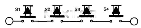
The total cost for all components is significantly lower than that of a heavy-duty DPDT foot switch. As indicated on the previous page, suggested electronic switch circuits can be easily constructed, and their applications are justifiable. New mechanical switches...
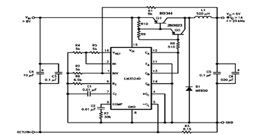
The schematic diagram below illustrates a 5V/1A Step-Down Switching Regulator utilizing the LM2524D Regulating Pulse Width Modulator (PWM). Additional parameters, PC board layout, stuffing diagram, and more information can be found in the LM2524D datasheet. The circuit design features the...
The reset switch on a computer is crucial. If an operating instruction threatens to disrupt the internal management of a computer, the reset button is often the only way to prevent a potential disaster. However, it can also lead...
This circuit can be used for multiple cameras with one monitor. The circuit can be operated manually or automatically. The described circuit functions as a video switching system, enabling the connection of multiple camera inputs to a single monitor output....
The following circuit illustrates a Power Factor Correction (PFC) Switching Power Supply Circuit Diagram. Features include suitability for 1U (1.75-inch) form factor and minimization of input harmonics. The PFC Switching Power Supply Circuit is designed to enhance the efficiency of...
This is a High Voltage switching device for driving coils and which have big impedance when it is switched off. It can be used in Back-EMF energy recovery tests, Newman coils electronic commutator. This device is driven by an...