
Electronics Circuits Reference Archive Audio LED VU meter
The circuit incorporates several key components and configurations that enhance its functionality in audio applications. The use of an 18V-0V-18V power rail allows for a balanced supply voltage, which is essential for audio fidelity. The feedback mechanism tied to the LED chain ensures that the visual output is consistent with the audio input level, providing a direct correlation between sound intensity and LED brightness.
The rectification process performed by the two op-amps allows for the conversion of the incoming audio signal into a usable form for further processing. The ability to switch between average and peak reading modes is crucial for different audio monitoring scenarios, enabling users to adapt to various audio signals effectively.
The logarithmic scaling achieved through the five-stage feedback circuit is particularly advantageous for audio applications, as it allows for a more intuitive representation of audio levels. This scaling helps in visualizing audio signals that can vary greatly in amplitude, thus facilitating better audio mixing and mastering processes.
The consideration for LED voltage characteristics in calibration is a vital aspect of the circuit design. By acknowledging the differences in voltage drops among various LED types, the circuit can maintain accuracy in its readings, thus ensuring reliable performance in professional audio environments.
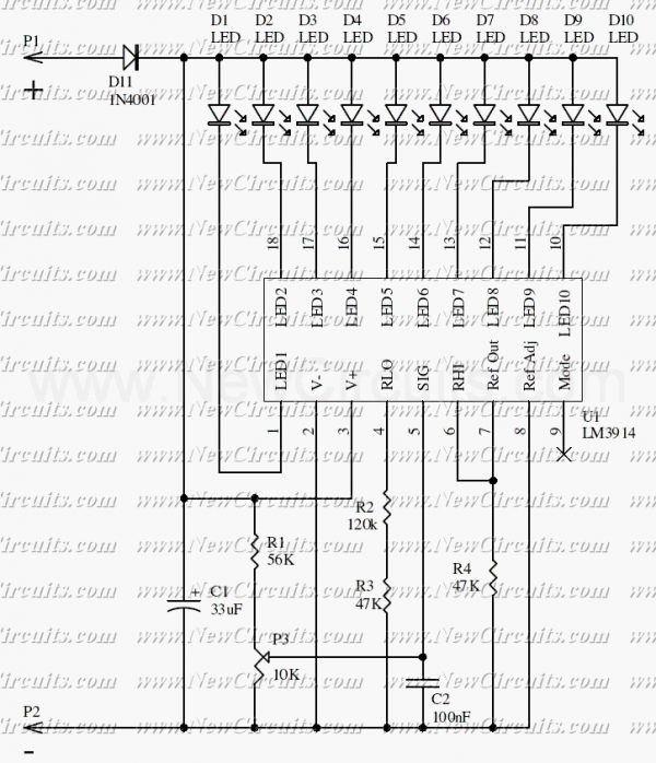
Overall, the circuit stands as a robust solution for audio level monitoring, with the potential for adaptation and improvement based on modern advancements in integrated circuit technology. The design reflects a thoughtful approach to combining discrete components for effective audio signal processing, which may still hold relevance in contemporary applications.The circuit was designed to work with an audio power amplifier which operated off 18v-0v-18v power rails. The actual voltage used is not too critical except that the feedback is referred to the LED chain which itself is anchored to a 12v rail, hence the separate stabilizer for this.
It has one large advantage over most of the LED chips available - all the LEDs are in series so it only draws 20mA irrespective of the number of LEDs illuminated. The two input op-amps form a rectifier circuit to rectify the audio input level. The changeover switch converts the circuit from average reading to peak reading. The third opamp stage gives a logarithmic scale: it does this by means of a 5 stage feedback circuit. The various stages of feedback are switched in by the LED operating voltages and the diodes and resistors feeding back to the ve input os the op-amp.
Clearly the calibration is going to be affected by the LED operating voltages: green LEDs are higher voltage than reds and high brightness LEDs drop more voltage than low. However my experience is that any particular make/type of LED are very consistent in voltage. This circuit was evolved quite some while ago for an audio mixing desk and it was put into production.
We were at that time trying to find an IC which would do the job. Once again the circuit using mostly discrete transistors worked out easier. This was however about 15 years ago and there are newer ICs which will do the job. However when I designed this circuit these were new and quite expensive. This is a circuit which 4QD could manufacture and sell if here were sufficient demand so if you do have a quantity application please contact us. Let me know if you have any queries or how you get on with it! We aim to transmit more information by carrying articles. Please send us an E-mail to wanghuali@hqew. net within 15 days if we are involved in the problems of article content, copyright or other problems.
We will delete it soon. 🔗 External reference
Related Circuits
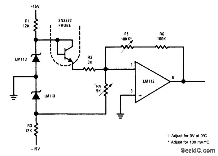
This simple circuit is an electronic thermometer that utilizes an inexpensive silicon transistor (2N2222) as the temperature sensor. The circuit provides an accuracy of better than 1°F over a 100°F range. An LM113 diode regulates the input voltage to...
A homemade photography LED array is being pursued, ideally configured as 6 series and 5 parallel, operating at 24 volts and 1000mA per row. Each LED row will emit a different wavelength, collectively covering the entire spectrum. The goal...
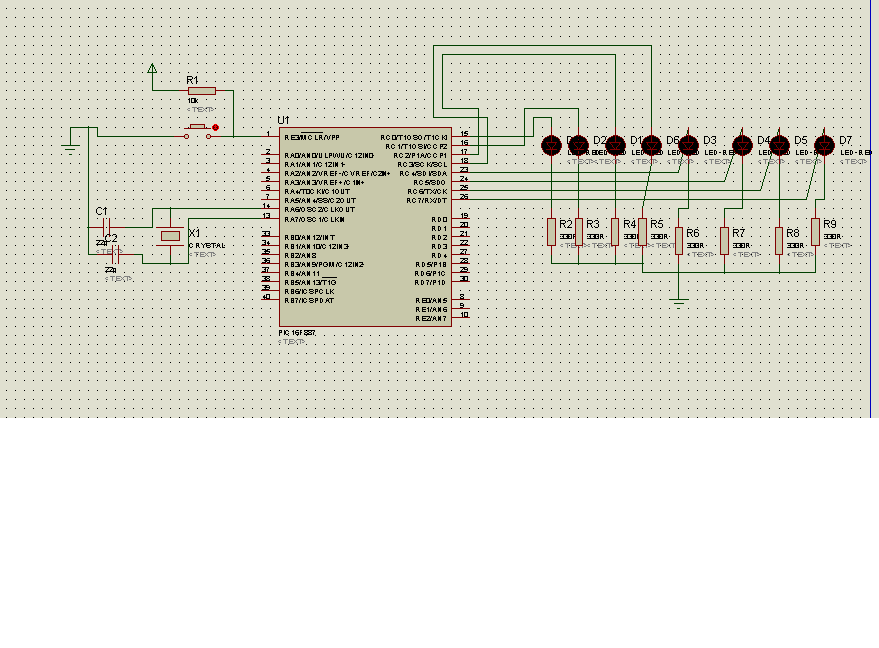
The code in mikroC PRO for the PIC16F887 microcontroller is designed to operate with an 8.000 MHz clock frequency on a Microchip 44-pin demo board. The routines have been developed using HITECH C, but the focus is on utilizing...
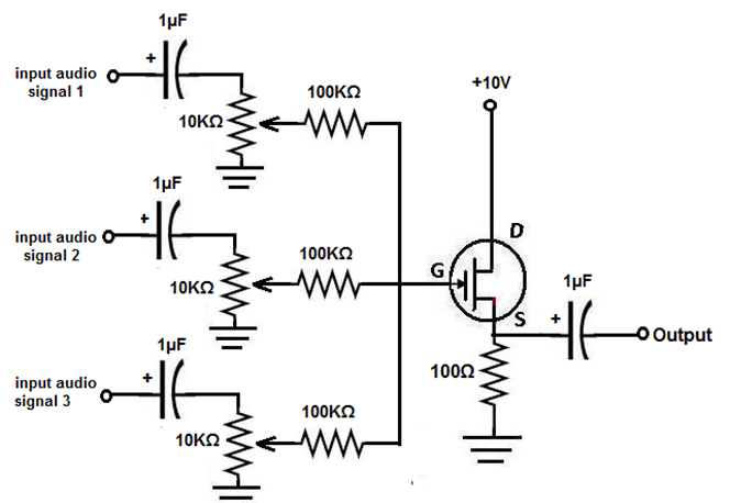
This project involves the construction of an audio mixer, a device designed to combine multiple audio signals into a single output. For instance, one input may consist of a solo vocal performance, while another could be background music. An...
This simple circuit makes it possible to monitor the charging process to a higher level. Final adjustments are simple and the only thing needed is a digital voltmeter for the necessary accuracy. Connect an input voltage of 12.65 volts...
The circuit presented is a 20W audio amplifier utilizing the LM1875 integrated circuit (IC). The LM1875 is a high-quality, low-distortion audio amplifier IC rated for 20 watts, available in a TO-220 package. This IC includes several built-in features such...
Warning: include(partials/cookie-banner.php): Failed to open stream: Permission denied in /var/www/html/nextgr/view-circuit.php on line 713
Warning: include(): Failed opening 'partials/cookie-banner.php' for inclusion (include_path='.:/usr/share/php') in /var/www/html/nextgr/view-circuit.php on line 713