
Audio Mixer
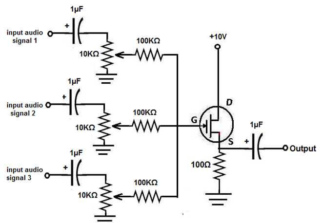
The audio mixer circuit can be broken down into several key components, each serving a specific function to facilitate the mixing process. The input stage consists of multiple audio inputs, which can be connected to various audio sources. Each input is accompanied by a coupling capacitor that ensures only the AC component of the audio signal is processed, effectively blocking any DC offset that could distort the output.
The resistors and potentiometers following the capacitors form the volume control section. The use of 10 kΩ resistors in tandem with 100 kΩ potentiometers allows for fine-tuning of each audio source's volume level. This configuration provides the user with the ability to balance the levels of multiple audio inputs before they are mixed together.
After the volume control stage, the mixed audio signals are combined and routed through another coupling capacitor to ensure that only the desired audio signal reaches the output. This final stage is crucial as it maintains the integrity of the audio signal, allowing for a clean and clear output.
The overall design emphasizes simplicity and cost-effectiveness, making it accessible for educational purposes and practical applications in audio mixing. The use of a JFET transistor in the circuit may be employed to provide additional gain and buffering, ensuring that the audio signals maintain their quality throughout the mixing process.
This audio mixer project serves as an excellent introduction to the principles of audio engineering, providing hands-on experience with fundamental electronic components and their applications in real-world scenarios.In this project, we will build an audio mixer, which is a device that can add different audio signals together into one output. For example, say, one audio input is a cappella, with a personG ‚¬ s lone voice singing and another audio signal is background music.
With an audio mixer, you can combine the background music with the singing to have a n output as if both audio signals were together, in other words, mixed, which is the function of a mixer. This project will serve to teach you about mixers and how they can be constructed cheaply using a few resistors, potentiometers, capacitors, and a JFET transistor.
It will do everything that a mixer is supposed to do: combine signals from different signal sources, with the capability of being able to change the volumes of the input signal sources as well as overall volume of the mixer output. A mixer is really nothing more than an adder. It adds all the different signals that are input into it and then combines the added signals into one.
The input audio signal inputs are where the audio signals which are to mixed enter the circuit. This could anything from microphone input, to a music audio file, to a speech file, any type of audio input which can be connected to this mixer. The 1G‚ µF capacitors which are directly after the audio signal inputs are coupling capacitors. These capacitors serve to only let the AC aspect of the audio signal through and block the DC aspect.
Only the AC aspect of the signal represents the audio of the signal. The DC is unwanted and would cause offset to the signal. Therefore, this is why we use these coupling capacitors. After these capacitors are 10KG resistors which are then hooked up to 100KG potentiometers. These 100KG potentiometers serve as volume controls. They control the volume of each individual audio signal which is input into the circuit. Turning the potentiometer so that its resistance increases lowers the volume of that audio signal. Conversely, turning the potentiometer so that its resistance decreases increases the volume of that audio signal. The 1G‚ µF capacitor on the output again serves as a coupling capacitor, so that only the AC signal goes to output and not any DC to cause offset.
The output signal contains all the audio signals tied into one channel, which is exactly how a mixer works. 🔗 External reference
Related Circuits
Audio metering is prevalent in various devices that play or record audio, ranging from cell phones displaying bar graphs of audio output levels to home stereos with flashing LEDs and live broadcasting equipment. Multiple standards exist for audio metering,...
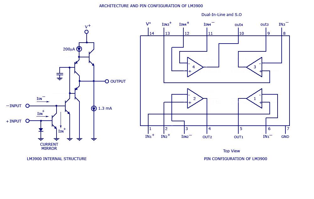
By adding the same circuit in parallel, the number of inputs can be increased according to the applications. Each input is connected to the inverting terminal of the LM3900. The built-in amplifier of each section amplifies every audio input...
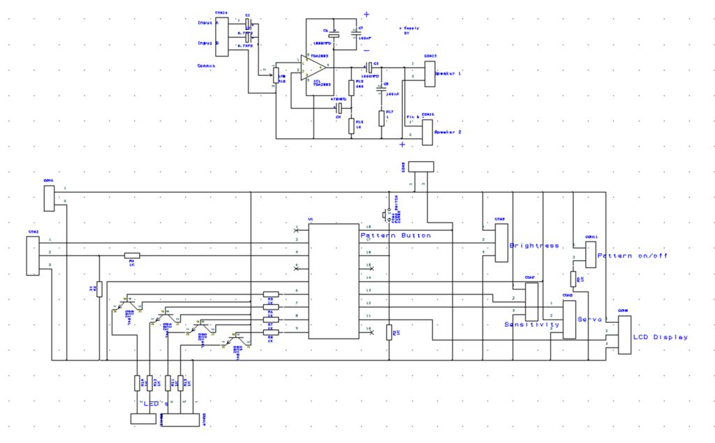
The hardware within this circuit involves a Picaxe 18M2 integrated circuit, which serves as the programmable microcontroller in the design and can be programmed using a PC. The Picaxe 18M2 microcontroller is a versatile device that is well-suited for a...
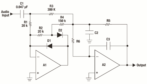
The goals were achieved by utilizing a discrete-components operational amplifier (op-amp) driving a complementary common-emitter output stage configured for Class B operation. In this configuration, for small output currents, the output transistors remain off, allowing the op-amp to supply...

A 3D enhancement is required to achieve a fully three-dimensional sound experience for most stereo multimedia products. Typically, simple phase-delay circuits are utilized to create a widening effect on the perceived sound field. However, this approach can lead to...
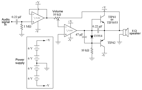
It is advisable to obtain TIP41 and TIP42 transistors, which are closely matched NPN and PNP power transistors with dissipation ratings of 65 watts each. If a TIP41 NPN transistor is unavailable, the TIP3055 (available from Radio Shack) serves...