
led blinking program with pic16f887
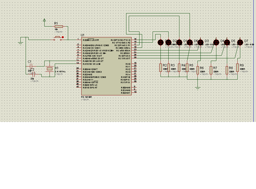
The PIC16F887 microcontroller is a versatile device featuring a 14-bit instruction set architecture, suitable for a wide range of applications. Operating at an 8.000 MHz clock frequency allows the microcontroller to perform various tasks efficiently. In this design, the internal oscillator is utilized to generate the necessary clock signal, which simplifies the circuit by eliminating the need for external clock components.
The microcontroller's GPIO (General Purpose Input/Output) pins can be configured to drive LEDs, providing visual feedback on the program's execution. Each LED can be connected to a specific port pin, allowing individual control over their states. The speed at which the LEDs are turned on and off can be adjusted by modifying the timing parameters in the code, which directly influences the delay between state changes.
The implementation of a micro switch introduces an interactive element to the circuit. This switch can be connected to another GPIO pin configured as an input. When the switch is activated, it can trigger a change in the LED behavior, such as reversing the direction of the LED sequence or altering the speed of the flashing pattern. This feature not only enhances user engagement but also serves as a practical exercise in handling input devices with the microcontroller.
The code written in mikroC PRO should include initialization routines for setting up the internal oscillator, configuring the GPIO pins as outputs for the LEDs, and setting up the input pin for the micro switch. A main loop will continuously check the state of the switch and update the LED states accordingly. Proper debouncing techniques should be employed to ensure reliable switch operation.
In summary, this project serves as an educational platform for understanding the operation of the PIC16F887 microcontroller, particularly focusing on the internal oscillator's control and the interaction between input and output devices. The implementation of the LED control and micro switch functionality provides a solid foundation for further exploration of embedded systems.The code in mikroC PRO for PIC16F887, with 8. 0000 MHz clock for microchip 44 pin Demo board, the routines have been written from microchip in HITECH C, since I am working and have programmer and software from mikroE I am interested to go with that only, instead of running around. If any body will help me for that, they used internal oscillator to control the speed of the running leds on one of the ports and the direction is switching with the help of one micro swith. This all I wand in mikroC PRO. , that will help me in learning the use and control of the internal clock of the MCU and other things as well.
🔗 External reference
Related Circuits
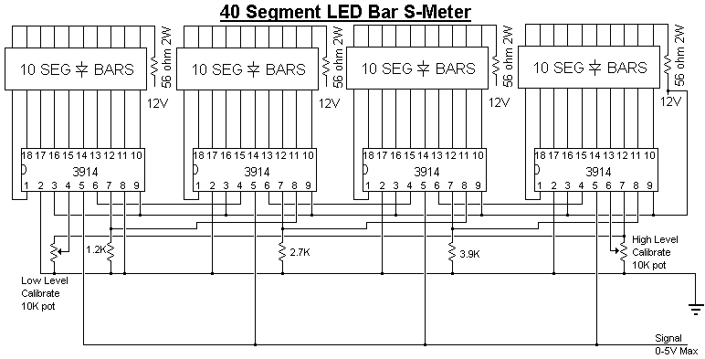
Provide your radio with an actual cord signal. First, adjust the HIGH LEVEL potentiometer to the point where all LEDs are illuminated. Then, completely remove the signal and adjust the LOW LEVEL potentiometer until no LEDs are lit. If...
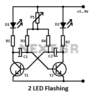
This is a simple flashing LED circuit featuring two LEDs and two NPN transistors. It demonstrates the behavior of transistors and capacitors, and it can be used in an oscillating configuration. The circuit consists of two NPN transistors, which function...
A total of 512 functional LEDs is required for the lattice assembly. These LEDs must be stable and bright. This section outlines the process for identifying faulty LEDs among the usable ones. Often, there are defective LEDs, particularly when...
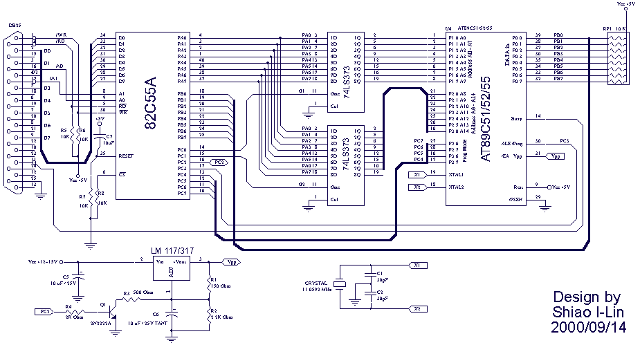
The Atmel Flash devices are ideal for developing, since they can be reprogrammed easy and fast. If you need more code space for your application, particularly for developing 89Cxx projects with C language. Atmel offers a broad range of...
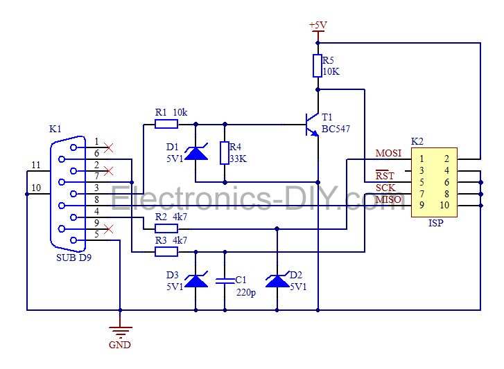
This is a simple AVR programmer designed for Atmel microcontrollers from the AVR family that support serial programming. The programmer connects to a PC via the RS232 serial interface and is compatible with PonyProg or Avrdude software. It is...

This analyst is a sensitive instrument in the frequency changes and width of an acoustic signal. Thus, the brightness of the LED that turns on each moment is proportional to the signal width, while the color is proportional to...
Warning: include(partials/cookie-banner.php): Failed to open stream: Permission denied in /var/www/html/nextgr/view-circuit.php on line 713
Warning: include(): Failed opening 'partials/cookie-banner.php' for inclusion (include_path='.:/usr/share/php') in /var/www/html/nextgr/view-circuit.php on line 713