
Multisound generator with description

The multisound generator circuit is designed to create a variety of audio signals, making it suitable for applications such as alarms, notifications, and sound effects in electronic devices. The core of the circuit typically consists of a microcontroller or a dedicated sound generation IC that can be programmed or configured to produce different tones and sound patterns.
The circuit may include components such as resistors, capacitors, and diodes which help shape the audio signals. A potentiometer can be incorporated to adjust the volume of the output sound, allowing for customization based on user preferences. Additionally, a speaker or piezo buzzer is connected to the output stage to convert the electrical signals into audible sound waves.
The power supply for the circuit can be derived from a battery or an external power source, ensuring that it operates efficiently. The layout of the circuit should be carefully designed to minimize interference and ensure clear sound output.
In terms of functionality, the multisound generator can be programmed to switch between different sound modes, enabling the user to select the desired sound for specific applications. This feature can be implemented through the use of push buttons or a rotary switch that allows for easy selection of sound profiles.
Overall, the multisound generator project not only demonstrates the principles of sound generation in electronics but also provides a practical application for creating engaging and varied audio alerts in various devices.Multisound generator is very interesting project in the series of alarm project multisound generator generates 8 different type of sound circuit diagram of.various electronics project. 🔗 External reference
Related Circuits

A video digitizer, also known as a frame grabber, captures still picture frames from a television set, video camera, or video recorder, and transmits them to a computer for display, storage, or manipulation. This document outlines the Mark II...
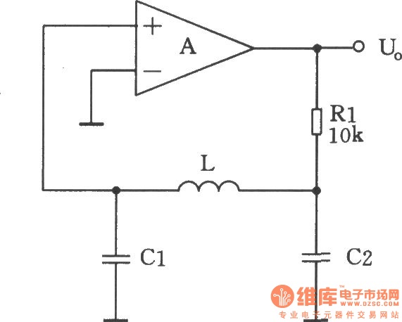
A square-wave generator utilizing an LC circuit can achieve improved frequency stability, as illustrated in the accompanying chart. This three-terminal capacitor oscillator is capable of generating a square wave, with an operational amplifier serving as the active component. The square-wave...
This circuit is effective for testing audio circuits using broadband noise. It employs three inexpensive C-MOS integrated circuits (ICs) that produce a series of output pulses with randomly varying widths. The audio noise generator is designed to drive earphones...
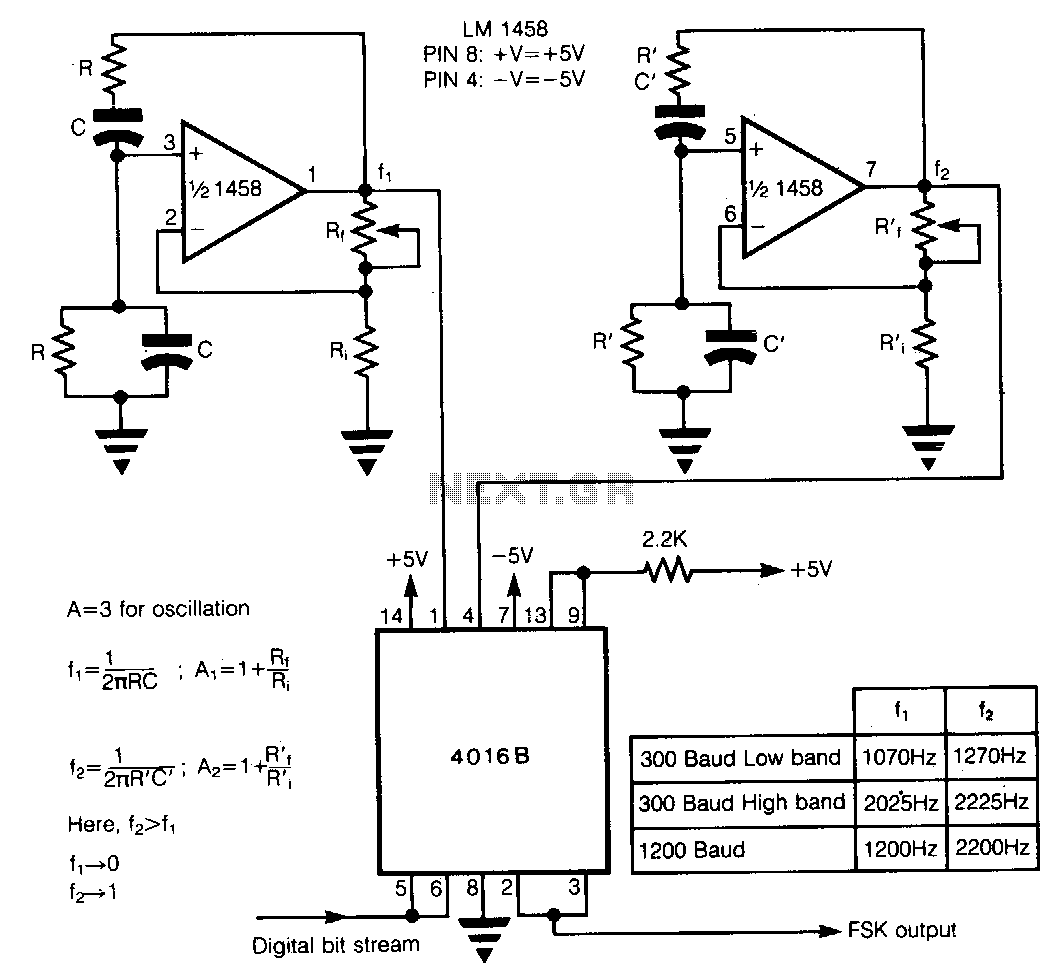
In Frequency Shift Keying (FSK), two distinct frequencies are utilized to represent the binary digits 0 and 1. The core of the circuit comprises two Wien-bridge oscillators constructed with a dual operational amplifier LM1458, each generating one of the...
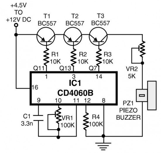
The circuit generates pulses of 1.25 Hz from pin 1 and 20 Hz from pin 14. The three output pins of IC1 are connected to the base terminals of transistors T1, T2, and T3 through resistors R1, R2, and...
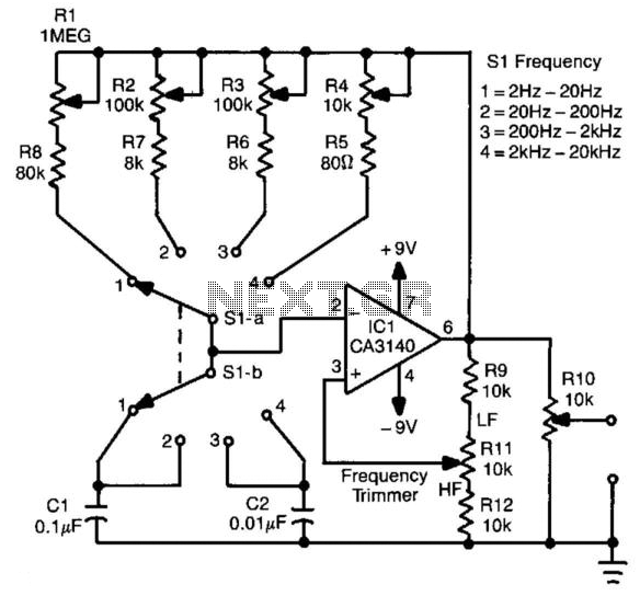
This circuit generates a square wave with a frequency range of 2 Hz to 20 kHz. It employs an operational amplifier in a relaxation oscillator configuration. The output voltage is approximately 15 V peak-to-peak. Resistors R1 through R4 serve...