
ems metaboard
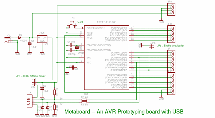
The circuit described is designed around an ATmega microcontroller, which can be selected from the ATmegaXX8 family, such as the ATmega328P. The microcontroller is configured to operate at various clock speeds, facilitated by an external crystal oscillator connected to the appropriate loading capacitors. The circuit includes provisions for USB communication, with Zener diodes used to protect the data lines from overvoltage, ensuring compatibility with both modern and older USB hosts. The optional reset switch enhances usability during development, allowing for easy resets without the need to disconnect power.
The design accommodates flexibility in component selection, allowing for different crystal frequencies and capacitor values based on availability. The inclusion of an ISP header supports firmware updates and debugging, while the breakaway header enables easy configuration for bootloader or application execution. The layout should be optimized for signal integrity, particularly for the USB data lines, to prevent interference and maintain reliable communication.
Overall, this circuit design is well-suited for prototyping and development purposes, providing a solid foundation for various applications while allowing for customization and enhancements as needed. Careful attention to component selection and layout will ensure a robust and functional electronic device.Any microcontroller in the ATmegaXX8 family should work, though if you`re going to go to the trouble of building this, spending a few tens of cents on extra flash memory seems like a prudent idea. A DIP socket is, strictly speaking, optional, but not having it is a genuinely bad idea. (Update: a 28-pin DIP socket is a bit of an oddball size. If you don`t have one handy, you can substitute a 20-pin socket plus an 8-pin socket. ) The 20pF caps are for loading the crystal. The cheap dipped ceramic kind work fine. You might be able to get away with 22pF if that`s what you have on hand (but make sure they match!). If you pick a different crystal speed, check the specs to find the right loading capacitor value. The crystal can be 12, 15, 16 or 20MHz. (Make sure you get one with at least five significant digits, e. g. 12. 000. ) You might also be able to substitute a three-pin crystal oscillator for the crystal and loading caps. The Zener diodes are there to clamp the USB D+ and D- voltages to 3. 6V (rather than the native 5V) when the AVR is driving the data lines. Most modern USB hosts deal with 5V on the data lines just fine, but some older ones do not. Not just any 3. 6V Zener diode will do; the high-current ones switch too slowly and distort the USB waveform too much.
Get the 1N5227B rated for 20mA Zener current. The pushbutton switch is for reset. It`s totally optional, but convenient. Use any junk-box normally-open switch you like. (I salvaged mine from a broken stereo receiver. ) The breakaway header should fit the kind of jumper you see on computer motherboards and hard disks. The jumper is there to let you select if the bootloader or application runs when power is first applied.
You could use an SPST toggle switch instead if you like. The least expensive source I found for the USB cable was to buy a USB "A" to "B" cable at the dollar store, then hack off the "B" end. I tied the cable to the circuit card with a zip tie for strain relief. The version in the picture has a six-pin ISP header. You can certainly add one if you like, though it probably won`t be much use unless you`re developing new bootloader firmware or doing in-circuit debugging or something.
Start by having a look at the Metaboard schematic (link goes to original Metalab site). My circuit is essentially the same, but without the provision for a separate power source, and none of the extra headers. There are many similar circuits around the `net, and variety is good. However, I`m not fond of the designs that regulate the USB +5V down to 3. 3V (using a couple diodes or a low-drop voltage regulator). My understanding is that the ATmega328P needs a Vcc of +5V for clock speeds over 10MHz. The picture at the top of the article shows the layout I used, which certainly works but isn`t really ideal.
(I`m especially offended by how I routed the D+ line - the white wire - under a resistor lead. ) It would probably be improved by swapping the vertical columns used by the D+ and D- stuff. The USB D+ line must be connected to a hardware interrupt (INT0 or INT1). USB D- and the jumper detect can go to any (two different) general-purpose IO lines. (Out of the box, the USBaspLoader software expects PD4 and PD7 respectively, so that`s what I used. ) Having a hardware reset line is optional, but makes the development cycle a lot more convenient. (You can flash, test, reset instead of flash, test, unplug, re-plug). If you need one more IO pin really badly, you can always disable reset in the fuses and use PC6 instead. I used small lengths of recycled component leads to jumper AGND to ground, AREF to Vcc, AVCC to Vcc and the four eight-pin rails in the prototyping areas to whichever of ground or Vcc was nearest.
This should be a good choice for most applications, but feel free to alter as needed. If you`re the careful sort, plug the newly-assembled board into a cheap USB power supply first, before risking an expensi 🔗 External reference
Related Circuits
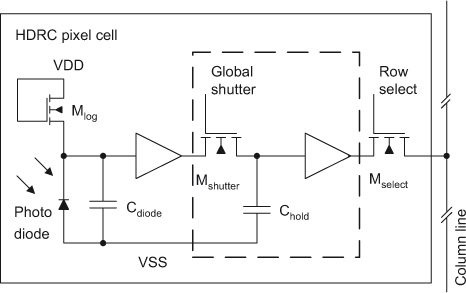
The initial section of this document outlines the high dynamic range CMOS (HDRC) imager, a specialized type of CMOS image sensor characterized by its logarithmic response. The significant capabilities of high dynamic range (HDR) image acquisition are explained through...
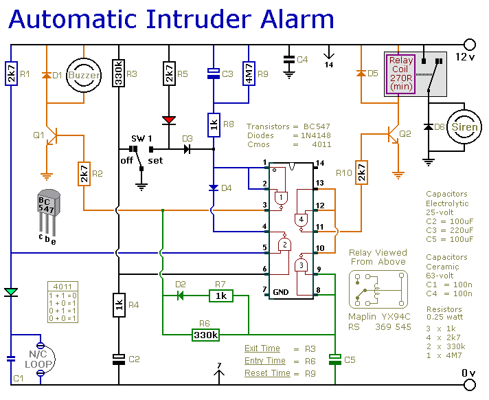
This is a simple single-zone home alarm system circuit. Its features include entry delays, a timed siren cut-off, and automatic exit. It is designed to be used with the usual types of normally-closed input devices such as foil tape,...
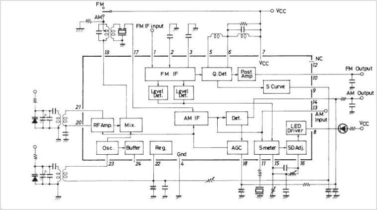
The LA1600 is an AM tuner integrated circuit (IC) housed in a 9-pin single in-line package (SIP). It provides the functionality of an AM tuner and is capable of operating within the shortwave (SW) band range. This IC is...
The 1-megohm resistor protects the FET from potential damage caused by accidental sparks to its gate lead. The circuit functions adequately without this resistor; however, it is advised not to intentionally apply a charge to the gate wire using...
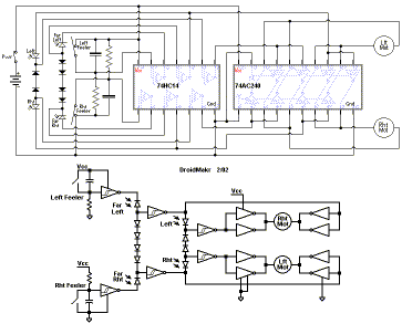
Voltage-controlled shape on each oscillator, calibrated 1V/octave keyboard input, external gate input socket, portamento/glide, patchable voltage inverter, extra input channels, improved panel components, power supply replacement, mains connectors. The described circuit features a voltage-controlled oscillator (VCO) architecture with several key...
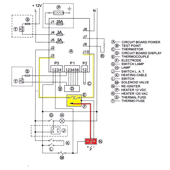
With the exception of pilot-type water heaters and some smaller LP/Electric refrigerators, modern LP appliances in RVs are controlled by electronics. Modern LP (liquefied petroleum) appliances utilized in recreational vehicles (RVs) have largely transitioned to electronic control systems, enhancing their...