
Group items tagged circuit Robotics

The circuit described integrates several key components to facilitate light detection and responsive movement. The FET gate protection resistor serves as a critical safeguard, ensuring the longevity and reliability of the circuit. The LED indicator provides immediate feedback on the operational status, illuminating when the circuit is functioning correctly and extinguishing in the presence of an external charge.
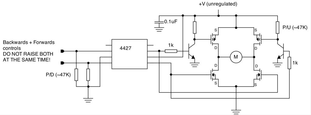
The robot's movement is governed by a series of photodiodes that detect light intensity, allowing for dynamic responses to environmental changes. The Master SC-H and Slave SC-H configurations enable the robot to navigate towards brighter light sources effectively, utilizing inverters that control motor functions based on light detection. The adjustable reverse time provided by the capacitor values allows for fine-tuning of the robot's behavior, making it adaptable to different environments and conditions.
The tactile switches add an additional layer of interaction, allowing the robot to respond to physical obstacles by reversing direction. This feature enhances the robot's navigational capabilities, ensuring it can maneuver around barriers without causing damage to itself or its surroundings.
Overall, the design demonstrates a sophisticated interplay between light sensing, motor control, and obstacle avoidance, resulting in a responsive and engaging robotic system. The careful selection of components and their arrangement within the circuit contribute to its functionality and effectiveness in various lighting conditions and physical environments.The 1-meg resistor helps protect the FET from being harmed by any accidental sparks to its Gate lead. The circuit will work fine without this resistor. Just don`t intentionally "zap" the Gate wire with a charged object or your charged finger. To test the circuit, charge up a pen or a comb on your hair, then wave it close to the little "antenna" wi
re. The LED should go dark. When you remove the electrified pen or comb, the LED should light up again. If you suspect that humidity is very high, test this by rubbing a balloon or a plastic object upon your arm. If the balloon does not attract your arm hairs, humidity is too high. When bumbing into something it can also reverse for several seconds. The time of going reverse can be changed. I`ve used 2M2 and 3, 3 uF, this will give a reverse time of about 5 seconds When you "power on" Bully it will first go backwards for some time.
After a few seconds it seems that it doesn`t know what to do, it looks like it`s shivering. Then it starts of going to the brightest lightspot it can see, first slowly and then like "in a hurry". In the time doing all this stuff, each bump into a obstacle makes it move backwards for a few seconds.
The time doing this can be changed with the 10 uF elco. Smaller means less seconds and bigger means reversing for more seconds. As long as the light reaching the photo-bridge of the Master SC-H is balanced, then the Slave SC-H acts as a regular, lone SC-H would. So, if one of the slave photo-diodes detects more light then the other, the inverter that controls the motor on that side changes states and is now the same as the inverter of the Master SC-H tied to the same motor.
This turns that motor off and the robot will pivot around the stopped wheel toward the greater light source until the light on each sensors is balanced and the motor again begins to turn. The Slave section has only two diodes (or one LED) between the photo-diodes. This makes it respond to smaller differences in light levels than does the Master part of the circuit Cheesy works very well.
I ve had fun making him chase a spot of light from a flashlight around on the floor. He has even been able to detect and react to the flashlight spot on the floor of the brightly lighted lab where I work. The tactiles switches behave even more strongly: if a switch is closed then the bot turns away unconditionally.
If both switches are closed the robots reverse straight back regardless of light level. From the title it would appear that all 4 photodiodes face forward but the 2 inner PD s face directly forward and the outer 2 are angled to the left and right 🔗 External reference
Related Circuits

A 12V car battery is recommended as the input for this circuit, utilizing the 2N3055 transistor as the amplifier. This configuration can deliver a power output of up to 100W, making it suitable for use in battery chargers, emergency...

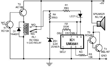
This musical light alarm circuit is very simple and uses only seven components, including a light-dependent resistor (LDR) and a 3.6V battery or three 1.2V rechargeable batteries. The well-known UM66 is utilized as the sound generator, providing a pleasant...
To create a versatile and generic microcontroller board, the information provided thus far is sufficient. It covers the essential components needed to achieve this. The design of a microcontroller board requires careful consideration of various factors to ensure versatility and...

The circuit comprises a low-distortion, 1-kHz oscillator designed to measure Total Harmonic Distortion (THD) at a user-selected voltage level, suitable for voltage amplifiers or for testing amplifiers with power levels up to 600 W. It is capable of detecting...
This heat detector alarm electronic project is designed using the UM3561 sound generator circuit and several common electronic components. The heat detector circuit employs a complementary pair of npn and pnp transistors to sense heat. When the temperature near...
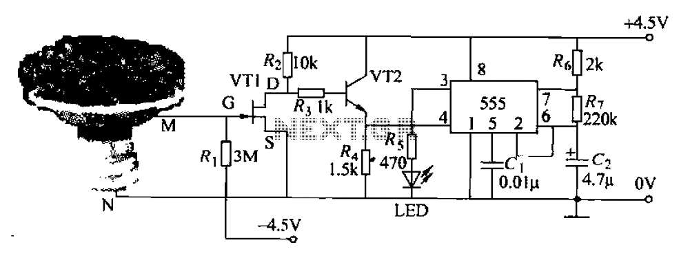
The flowers in pots require watering, as relying solely on the observation of moist soil surfaces can be unreliable. To address this issue, a flower watering indicator has been developed. This circuit includes a field effect transistor (VT1), a...