
Enclosure for the Magnetometer v2.0

The enclosure for the magnetometer serves as a critical component in ensuring the integrity and accuracy of the measurements taken by the device. The design emphasizes both thermal stability and magnetic cleanliness, which are essential for the precise operation of a magnetometer. The wooden frame provides structural support, while the choice of insulating materials helps maintain the desired internal temperature. The integration of a temperature controller allows for active management of the internal environment, ensuring that fluctuations in external conditions do not adversely affect the instrument's performance.
The digital link established for data transmission is another vital feature, enabling real-time monitoring and analysis of the magnetometer's readings. This connection facilitates immediate access to data, allowing researchers to respond quickly to any anomalies or required adjustments in the measurement process.
The construction techniques employed, such as the use of readily available materials and the incorporation of insulation and sealing methods, reflect a practical approach to building an effective environmental chamber. The use of Styrofoam and acrylic sealant not only provides thermal insulation but also protects against moisture ingress, which could compromise the magnetometer's functionality.
In summary, the enclosure's design and construction are tailored to create an optimal environment for the magnetometer, ensuring reliable operation and data collection in an outdoor setting. The careful consideration of temperature control, material selection, and structural integrity contributes to the long-term success of the magnetometer's deployment in a magnetically clean and thermally stable environment.The magnetometer was moved to an outdoor location and a specialized enclosure was built. An accessory temperature controller was included to maintain a constant temperature and digital link was created to ferry the recorded data back into the laboratory. During the August-September 2000 refurbishment, the magnetometer was moved from the thermally stable but magnetically
dirty basement laboratory to new magnetically cleaner but thermally unstable location outside and away from any building. Of course, it could not be left outside exposed the elements so an enclosure was built to provide a controlled environment.
An accessory temperature controller was included to maintain a constant temperature and digital link was created to ferry the recorded data back into the laboratory. The enclosure can be seen in the accompanying images in various states of assembly to show the different techniques used in its construction.
Many of the materials can be found around the house or at a local hardware store at a modest cost. Approximately 4`x3`x2` (LxWxH) in external dimensions, the enclosure consists of a wooden frame built with two-by-two stock covered on the four sides with 0. 25" thick plywood, chip board, or particle board (whatever was available in the junk box. The top was left open to accept a 0. 25" thick plywood lid; the bottom was also left open to accept a false floor. The vertical two-by-twos extended about 6" below the sides with pointed tips and were driven into the ground for anchoring.
A quiet, shaded location was found beneath a large native Colorado Blue Spruce tree which was cleared of dead branches. The ground was leveled and excavated to a depth of a few inches. a layer of heavy vinyl plastic was placed over the excavation, small undersized cuts were made at the locations of the vertical stakes and the enclosure was driven home and roughly leveled using a heavy hammer.
The soil surrounding the base was mounded up against the walls and the vinyl was left draped over the mound. The inside of the walls was filled with 1. 5" thick styrofoam construction insulation and held in place with plenty of constructive adhesive. a false floor from another piece of 0. 25" particle board cut about one inch smaller than the interior of the enclosure. Three two-by-two stakes were driven through small cuts in the vinyl, leveled, and the floor space filled with styrofoam "peanuts".
The false floor was screwed down onto the stakes and the gaps at the edges filled with self-expanding insulating foam which was trimmed back after hardening. The outside walls were sealed against moisture using many spray cans of clear acrylic sealant. Any gaps in the insulation on the walls was touched up with the self-expanding foam. The result is a draft free, physically stable, and clean chamber. The lid was also sealed on the outside with acrylic and lined on the inside face with 1. 5" thick styrofoam as with the walls. The top surface of the walls was lined with weather stripping to ensure a good seal with the lid. When the lid is fitted in place another piece of vinyl is placed over the whole enclosure and held in place with a piece of light rope.
This provides for a rain shield and helps reduce any drafts due to gaps near the lid. After the completion of the construction it was necessary decide upon an operating temperature for the interior of the enclosure and to design a device for maintaining that temperature. There are several design considerations which go into the selection of the operating temperature. It must be high enough so that regulation can be maintained during the heat of summer. It must be a low as possible to require the smallest size of heater. It must also be as low as possible to reduce the temperature induced degradation of the electronic components used in the chamber.
a temperature of approximately 28 °C (82. 4 °F) was finally chosen; high enough to 🔗 External reference
Related Circuits
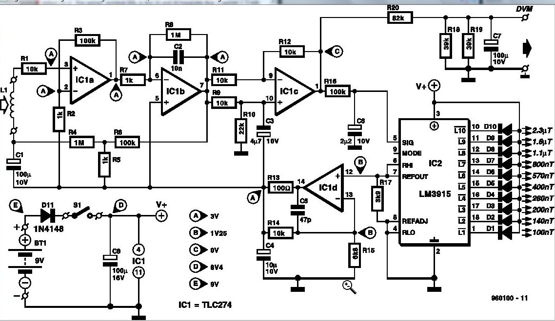
Some experts believe that static magnetic fields (SMFs) may affect the physical well-being of individuals. If one subscribes to this viewpoint, the magnetic-field meter described here will aid in locating sources of SMFs and assessing their strength. These results...
This Atmel integrated circuit operates at a clock frequency of 12 MHz, facilitating communication between an infrared receiver and a personal computer. This setup enables the processing of signals by infrared receiver software, such as Girder. When a valid...
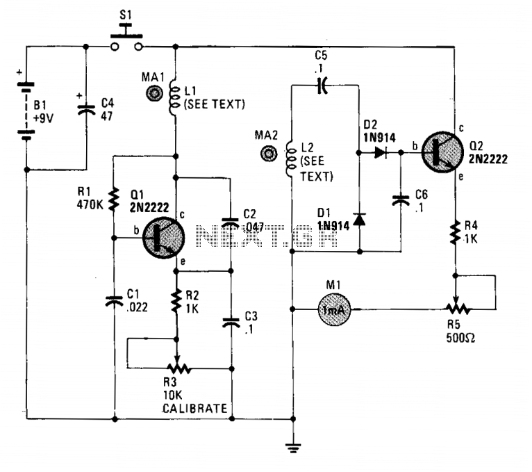
The circuit employs two general-purpose NPN transistors, Q1 and Q2, along with a specially designed hand-wound dual-coil probe to detect magnetic fields. Q1, along with its associated components, forms a simple Very Low Frequency (VLF) oscillator circuit, with L1,...
This is an enhanced version of the Darkroom Timer initially developed by Stan Ockers in 1999. Additional features have been incorporated, and the PIC code has been accordingly modified. The complete schematic, PCB layout, and silkscreen are provided in...