Magnetometer

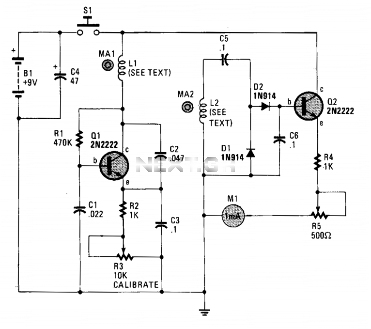
The circuit employs two general-purpose NPN transistors, Q1 and Q2, along with a specially designed hand-wound dual-coil probe to detect magnetic fields. Q1, along with its associated components, forms a simple Very Low Frequency (VLF) oscillator circuit, with L1, C2, and C3 determining the oscillation frequency. The VLF signal captured by the pickup coil, L2, is filtered through capacitor C5 and subsequently rectified by diodes D1 and D2. The small DC output signal from the rectifier is directed to the base of Q2, which is configured as an emitter follower, and this output is then used to drive a 0-1 mA meter, M1.
The circuit operates by utilizing two NPN transistors, Q1 and Q2, where Q1 functions as the oscillator while Q2 serves as a signal amplifier. The oscillator circuit is critical for generating a VLF signal, which is influenced by the inductance of coil L1 and the capacitance values of capacitors C2 and C3. The specific frequency of oscillation can be adjusted by altering these component values, allowing for flexibility in the circuit's sensitivity to different magnetic field strengths.
The dual-coil probe, designed for this application, is capable of detecting variations in magnetic fields, which are then converted into an electrical signal. The first coil, L1, generates the VLF signal, while the second coil, L2, acts as the sensor that picks up the induced signal from the magnetic field. Capacitor C5 serves to smooth out the rectified output from the diodes D1 and D2, ensuring that the signal fed into Q2 is stable and suitable for amplification.
Q2, configured as an emitter follower, provides a high input impedance and low output impedance, which is ideal for driving the 0-1 mA meter, M1. This configuration allows for accurate representation of the detected magnetic field strength on the meter, with the output current proportional to the input signal from the rectifier. The overall design of the circuit emphasizes simplicity and effectiveness in detecting and measuring low-frequency magnetic fields, making it suitable for various applications in electronics and physics.The circuit uses two general-purpose npn transistors, Ql and Q2, and a special hand-wound, dual-coil probe ferrets out the magnetism. Ql and its associated components form a simple VLF oscillator circuit, with LI, C2, and C3 setting the frequency.
The VLF signal received by the pickup coil, L2, is passed through C5 and rectified by diodes Dl and D2. The small dc signal output from the rectifier is fed to the base of Q2 (configured as an emitter follower), which is then fed to a 0-1 mA meter, Ml.

