
Magnetic Field Meter Magnetometer Circuit
The magnetic-field meter is designed to provide a reliable means of detecting and measuring static magnetic fields, which are of increasing concern in various health discussions. The operational amplifiers play a critical role in ensuring that the weak signals from the induction coil are amplified sufficiently for accurate measurement. The choice of components, such as the feedback network and the rectifier configuration, contributes to the circuit's stability and accuracy, allowing it to function effectively within the specified frequency range. Additionally, the integration of a display driver with LED indicators enhances user interaction by providing immediate visual feedback on the field strength detected. This meter can be particularly useful in environments where exposure to SMFs is a concern, enabling users to make informed decisions regarding their exposure levels. The inclusion of a DVM connection further extends the functionality of the device, allowing for precise digital readings of the magnetic field strength. Overall, this circuit represents a sophisticated approach to monitoring static magnetic fields, combining ease of use with technical efficiency.Some experts` think that SMFs may affect the physical well-being of people. If you believe that these experts are right, the magnetic-field meter described will help you find sources of SMFs and determine their strength. These findings may help you reduce the field strength. The input amplifier, based on IC1a, ensures that the signal from the induction coil, L1, is amplified x 101.
The coil is terminated into a high impedance, so that its output is buffered by the op amp. The integrator consists of IC1B, another of the four op amps contained in IC1. The (active) rectifier, based on IC1c, is, in fact, a differential amplifier that lessens the average voltage by the output potential of the integrator. Since the op amp is powered asymmetrically, the output is a half-wave rectified alternating voltage. This voltage is averaged by R16-C6 or, in case a DVM is used as the meter, by R18-R20- C7. The form factor (2. 22) is corrected by the rectifier. The level matching is purposely carried out by the rectifier since this op amp has a much larger swing than IC1a or IC1b.
The principle of the present meter is shown in the block diagram in Figure 1. The induction coil used to detect the magnetic field is represented by an alternating- voltage source, V1, whose average output is 1 µV. The output of the source is amplified x 101 by op amp X1. The op amp is linked to integrator X2 which provides frequency-dependent amplification. For direct-voltage signals this is 1000, for high-frequency signals it is 0. The cross-over frequency is chosen so that the amplification is uniform over the range in which magnetic induction is to be measured (40 Hz 10 kHz).
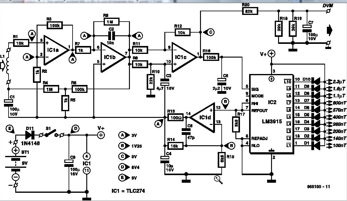
Feedback network R4-R6 automatically ensures that the circuit has a stable d. c. operating point at all times. This makes it possible for relatively inexpensive op amps to be used. Also, the internal attenuator ensures that the maximum d. c. amplification is x 101 (1+R6/R5). The value of R6/R5 also determines the lower limit of the frequency range. The circuit diagram of the meter is shown in Figure 2. It consists of an input amplifier, integrator, automatic offset correction network, rectifier with d. c. suppression, display and associated drive, power supply, and a socket for connection to a digital voltmeter (DVM).
Op amps IC1a and IC1b carry a pure sinusoidal signal that alternates symmetrically around a direct voltage of 3 V, whereas that of IC1c alternates around 0 V. This means that this op amp can handle an amplification of x 2. 2 much better than the earlier two. The drop across C6 is used by the display driver, IC2, to represent the strength of the magnetic field.
The driver has its own reference-voltage source. This 1. 25 V source is also used to derive an auxiliary voltage for op amps IC1a and IC1b. The potential at node A is [ ( R14 + R15 ) / R15 ] x 1. 25 = 3 V. The minimum voltage at which IC2 provide full drive is 1. 2 V. Since the IC is driven by an averaged potential, the signal level required for full drive is 1. 2 x Pi = 3. 77 Vpp. Because the signal amplification takes place in the rectifier, that is, the op amp with the largest drive range, a drop in battery voltage does not immediately affect the accuracy of the meter. The display driver controls ten LEDs. The diagram clearly shows which LED lights at a given fieldstrength. When D10 lights, the measured fieldstrength >=2. 3 µV, rather greater than the upper limit specified in MPRII (250 nT). If the meter is linked to a DVM, this must be set to its 200 mV direct- voltage range. The measurement range is then 50 nT 2 µT. Measuring levels below 50 nT is not possible o 🔗 External reference
Related Circuits
Multi Tone Alarm Description This is a simple and easy-to-build multi-tone alarm circuit that can be used in burglar alarms or sirens. The circuit is based on the dual op-amp MC1458 and LM380. The two op-amps inside the MC1458...
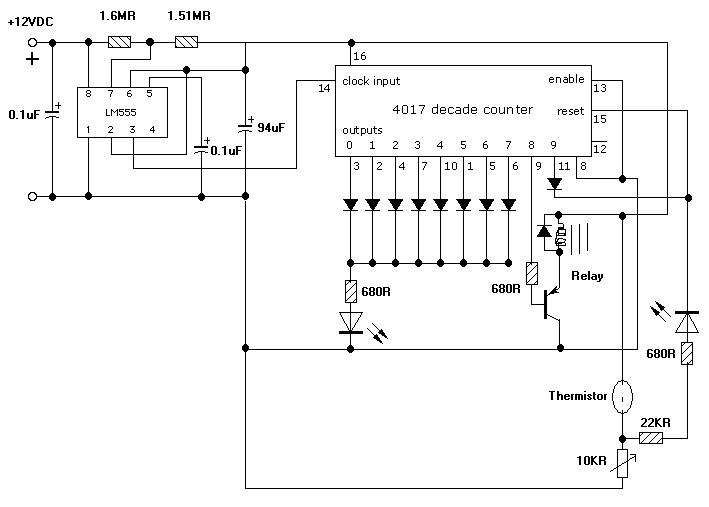
A simple tool to check the degree of radiation from an electric or electronic instrument. The LEDs in the circuit will provide a running light pattern when the circuit detects electromagnetic radiation from the device. It can identify radiation...
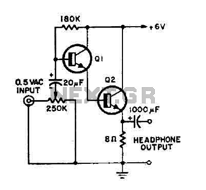
This is a simple headphone amplifier. Any NPN transistor can be used. The circuit can be powered by a 9V battery. The headphone amplifier circuit serves to boost audio signals to a level suitable for driving headphones. It typically consists...
I am looking to build a timer for a pump. I want the pump to run for 5 minutes, then stop. To create a timer circuit for a pump that operates for a duration of 5 minutes, a simple astable...
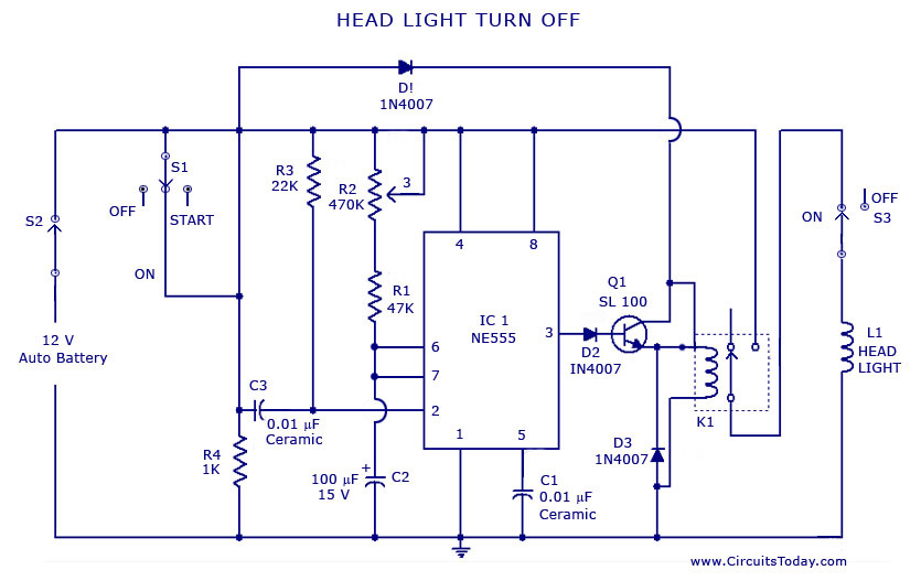
A circuit that can automatically turn off the headlights or lamps of a vehicle after a preset time. This light switching circuit is constructed using a 555 timer integrated circuit (IC). The described circuit utilizes the 555 timer IC in...
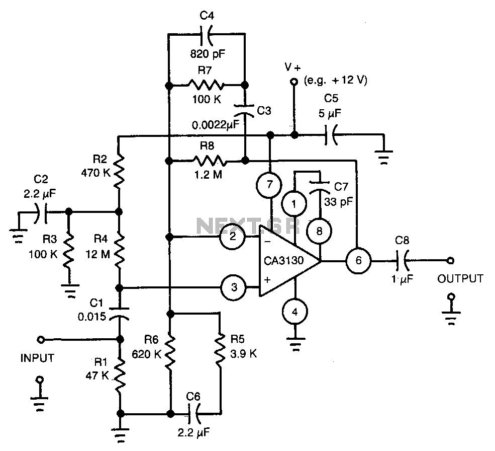
This circuit utilizes a CA3130 BiMOS operational amplifier. The amplifier is equalized to meet RIAA playback frequency response specifications. It serves as a preamplifier following a magnetic tape head. The circuit employs the CA3130 BiMOS op-amp, which combines the benefits...
Warning: include(partials/cookie-banner.php): Failed to open stream: Permission denied in /var/www/html/nextgr/view-circuit.php on line 713
Warning: include(): Failed opening 'partials/cookie-banner.php' for inclusion (include_path='.:/usr/share/php') in /var/www/html/nextgr/view-circuit.php on line 713