
Energy Saving Lighting with One-Shot Timer Circuit
The first circuit, utilizing the relay, allows for straightforward control of the lighting system. The relay acts as a switch that can handle high voltage and current, making it suitable for household lighting applications. The 555 timer is configured in a monostable mode, where the timing interval can be adjusted by changing the values of R1, C1, and R2. When the switch is activated, the timer begins counting, and after the predetermined time (approximately 4 minutes), the relay deactivates, turning off the lights.
In the second circuit, the use of the MOC3041 optoisolator triac provides electrical isolation between the control circuit and the high-voltage AC mains, enhancing safety. The BTA06-600 triac serves as the main switching element, allowing for efficient control of the AC load. The 555 timer functions similarly to the first circuit, controlling the duration of the light activation. The design of this circuit also allows for dimming capabilities if additional components are integrated.
Both circuits require careful assembly to ensure safety and functionality. Proper heat dissipation should be considered for the triac and relay, as they may generate heat during operation. It is advisable to include fuses or circuit breakers in the design to protect against overload conditions. Furthermore, the enclosures for these circuits should be adequately ventilated to prevent overheating and should be rated for electrical components to reduce the risk of fire hazards. Overall, these energy-saving circuits present an effective solution for managing lighting duration while minimizing electricity costs.Faced with the situation to control the time that the light is turned on, engineer Radu Preda from Romania has started experimenting with different circuits to save money spent on electricity. He has designed 2 energy saving lighting circuits, the first one uses a relay and the second one uses a optoisolator triac MOC3041 and a normal triac like B
TA06-600 and both using the 555 one-shot timer. Note that the circuit is coupled directly to AC mains using the existing system in the building. A switch is used to start the timing and light one or more bulbs. The relay is powered from 12V and its contacts must outstand up to 1kW at 220V. With the values from the schematic the working time of the lighting circuit is around 4 minutes. Power is applied through R1, C1, R2 and the voltage is stabilized at a value of 15V with the zener diode PL16Z. The second schematic uses the same timing block but the control element is the BTA06-600 triac. Please be careful in constructing and utilizing these circuit because there is danger of electrical shock.
Assemble it in plastic or metal box and place it in places inaccessible to children or animals. Obviously, must be protected from rain and solar radiation that adversely affect the proper functioning. 🔗 External reference
Related Circuits
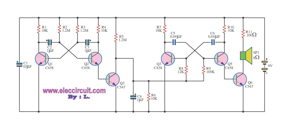
This circuit generates a sound similar to that of ambulance sirens. It differs from typical ambulance siren circuits in its design. The circuit utilizes a combination of oscillators and amplifiers to produce a sound that mimics the varying pitch and...
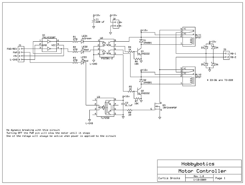
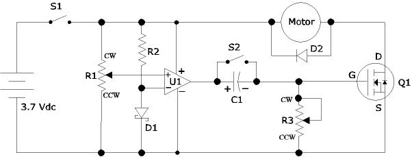
Develop a cost-effective high-current circuit that utilizes PWM. The design includes flyback diodes to protect the MOSFET from the back EMF generated by the motor when the power is switched on and off via the PWM signal. This configuration...
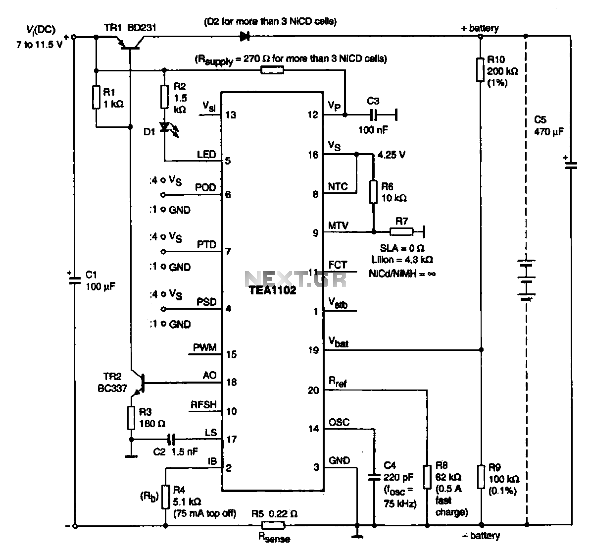
A fast charging circuit utilizing the TEA1102 controller is designed for various battery types. This circuit operates with a DC power supply voltage ranging from 7 V to 11.5 V and is compatible with nickel-cadmium, nickel-hydrogen, and lithium-ion batteries. The...
The following circuit illustrates an Airplane Flight Timer Circuit Diagram. Features include switches in the closed position and battery voltage maintained at a safe level. The Airplane Flight Timer Circuit is designed to provide a reliable timing mechanism for monitoring...
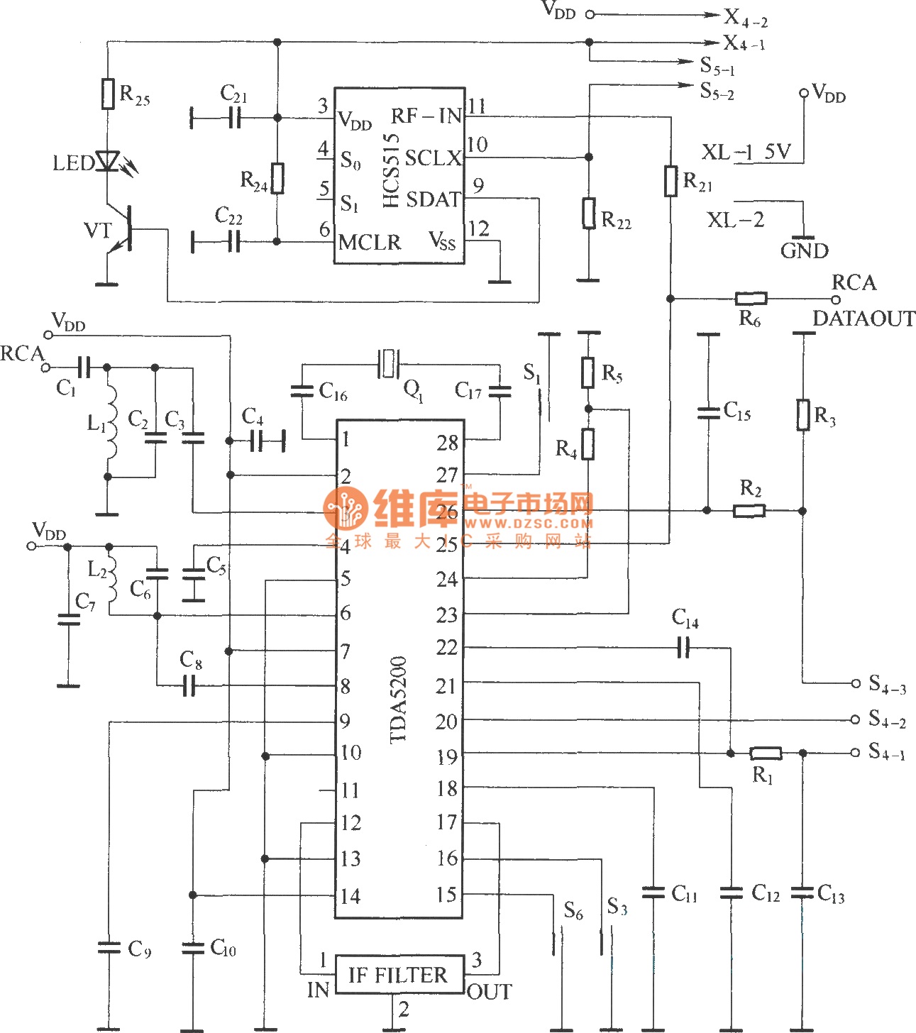
The TDA5200 is a low-power, single-chip ASK superheterodyne receiver circuit. It operates within two frequency blocks: 868 to 870 MHz and 433 to 435 MHz. This circuit is highly integrated, requiring minimal external components while offering excellent functionality. It...
To celebrate the hundredth design posted to this website and to fulfill the requests of many correspondents wanting an amplifier more powerful than the 25W MosFet, a 60 - 90W high-quality power amplifier design is presented here. The circuit...
Warning: include(partials/cookie-banner.php): Failed to open stream: Permission denied in /var/www/html/nextgr/view-circuit.php on line 713
Warning: include(): Failed opening 'partials/cookie-banner.php' for inclusion (include_path='.:/usr/share/php') in /var/www/html/nextgr/view-circuit.php on line 713