
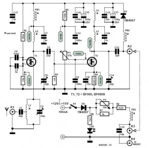
Ensemble II VHF RX rf
The circuit begins with a VHF antenna that captures incoming radio frequency (RF) signals. The RF signal undergoes a preamplification process to boost its amplitude, followed by filtering to eliminate unwanted noise and interference. The processed RF signal is then input to a Double Balanced Mixer (DBM), where it is designated as the "RF" signal. Concurrently, the mixer receives a Local Oscillator (LO) signal, which is generated prior to the Quadrature Clock Generator by an onboard microcontroller.
The mixing of the RF and LO signals produces an Intermediate Frequency (IF) output that contains both sum and difference components. In typical operation, the sum component is filtered out, allowing only the difference component to pass through to the next stage, which is the Quadrature Sampling Detector (QSD).
As a practical example, if the VHF signal of interest is at 145.200 MHz, the LO is set to 116.16 MHz. The DBM processes these signals, resulting in a difference frequency of 29.04 MHz, which is the frequency that the QSD will analyze. If the software-defined radio (SDR) system is configured with a center frequency of 145.200 MHz, the output frequency observed at the QSD will correspond to the difference frequency of 29.04 MHz. This process is crucial in radio frequency communication systems, enabling the effective demodulation and processing of signals within the desired frequency range.This stage begins at the VHF antenna. The incoming VHF RF signal is preamplified and filtered and presented as the "RF" signal to the ADE + Double Balanced Mixer (DBM). That mixer also accepts the Local Oscillator `s output (BEFORE the Quadrature Clock Generator ) as the "LO" input.
The two signals, "RF" and "LO" are then mixed to result in the "I F" output of the DBM. This output contains the sum and difference products of mixing the two inputs. The sum component is filtered out, sending the difference component into the Quadrature Sampling Detector (QSD) stage. For example, assume that the VHF signal of interest is at a frequency of 145. 200 MHz. Thanks to the firmware in the on-board microcontroller in the LO stage, the LO will produce an output of 116.
16 MHz. The DBM accepts the preamplified and filtered incoming RF signal at 145. 200 MHz along with the LO signal of 116. 16 MHz, to produce a signal with sum and difference components: The sum ( £) is discarded and the difference ( ” = 29. 04 MHz) is sent to the QSD stage. If the SDR software was configured to set the center frequency at 145. 200 MHz, then it would manifest itself in the QSD as 29. 04 MHz. 🔗 External reference
Related Circuits
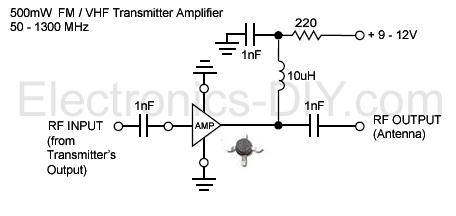
This is an aerial achievement low noise 500mW amplifier/booster designed for low power FM transmitters such as BA1404, BH1417, BH1415, and 433MHz transmitter modules. The amplifier utilizes a chip that incorporates various transistor stages and all necessary components within...
I have had requests to add a VHF FM transmitter, to the QRP collection. This project is a simple transmitter using only one crystal and will cover 145.00 to 146.00 MHz. The crystal is a 44.9333 MHz crystal for...
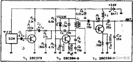
The circuit functions as a frequency modulation (FM) transmitter that operates within the 76 to 90 MHz FM radio band, commonly referred to as a wireless microphone. It receives signals through an FM radio receiver. The circuit is capable...
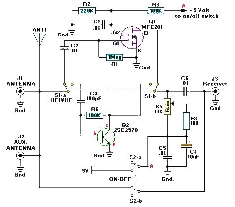
A simple and efficient active antenna electronic project can be designed using this electronic schematic circuit based on transistors. This active antenna project is effective for a wide range of RF frequencies, covering three RF bands: HF, VHF, and...
Along with a suitable directional antenna, this high-performance two-stage antenna amplifier for the VHF FM broadcast band will allow for the reception of distant signals. This two-stage antenna amplifier is designed to enhance signal reception in the VHF FM broadcast...
Here is a nice little receiver for narrow-band FM reception. It can also be used to receive FSK, RTTY and PACKET signals from the HF bands. Basic receiver sensitivity is in the region of 1uV PD and the receiver...
Warning: include(partials/cookie-banner.php): Failed to open stream: Permission denied in /var/www/html/nextgr/view-circuit.php on line 713
Warning: include(): Failed opening 'partials/cookie-banner.php' for inclusion (include_path='.:/usr/share/php') in /var/www/html/nextgr/view-circuit.php on line 713