
VHF FM transmitter
The modulator is a simple circuit which I will post later. Two OP-Amps were used in the prototypes, the first was a MIC amplifier to bring the MIC AF OP up to 500mV RMS. Clamp the AF with a couple of back-to-back diodes (limiter) then the second OP-Amp amplifies the clipped AF to the correct level, (about 1.5v RMS) for 5KHz deviation. Adjust the gain of the first OP-AMP for MIC GAIN and adjust the gain of the second OP-AMP for deviation (with FULL AF).
The output of the driver will supply about 10-20mW to the PA. I didn't use a PA because I lived so close to the repeater (path loss = -109dB). There are hundreds of VHF QRP PA's published in SPRAT, INTERNET, RSGB books, RadCom, and PACKET RADIO so I will leave that to your own ingenuity. A single transistor, such as the 2N3866 will be more than adequate to get up to 250mW, but an additional band-pass tuned circuit should be used between them.
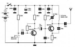
This VHF FM transmitter project is designed for operation within the 2-meter amateur radio band, specifically covering frequencies from 145.00 MHz to 146.00 MHz. The heart of the transmitter is a crystal oscillator utilizing a 44.9333 MHz crystal, which is a common frequency for various radio equipment. The choice of this crystal allows for effective frequency multiplication to achieve the desired VHF output.
The circuit employs a frequency multiplication technique, utilizing a conventional receiver multiplier stage that multiplies the input frequency by three, combined with a 10.7 MHz variable frequency oscillator (VFO). This configuration enables the generation of the necessary VHF signal while maintaining true frequency modulation (FM).
For modulation, the project incorporates two operational amplifiers (OP-Amps). The first OP-Amp acts as a microphone amplifier, boosting the audio frequency (AF) signal to approximately 500 mV RMS. To prevent signal distortion, two back-to-back diodes are used as a limiter, ensuring that the audio signal remains within a manageable range. The second OP-Amp further amplifies the limited AF signal to about 1.5 V RMS, suitable for achieving a frequency deviation of 5 kHz.
The transmitter's output stage is designed to deliver an output power of approximately 10 to 20 mW to the power amplifier (PA). While a PA is not included in the design due to proximity to a repeater, it is advised that users explore existing literature for suitable VHF QRP power amplifier designs. A recommended component for those looking to increase output power is the 2N3866 transistor, which can achieve power levels up to 250 mW. It is essential to include a band-pass tuned circuit between the driver and the PA to ensure efficient operation and minimize unwanted emissions.
The overall design emphasizes simplicity and ease of assembly, making it accessible for enthusiasts looking to explore VHF FM transmission without the complexity of multi-channel tuning.I have had requests to add a VHF FM transmitter, to the QRP collection. This project is a simple transmitter using only one crystal and will cover 145.00 to 146.00 MHz. The crystal is a 44.9333 MHz crystal for 145.500 receive, as used in the Trio (Kenwood) 2200, PYE, Motorolla, Tait equipment, to name but four. The frequency of the crystal is not critical as almost any other xtal for the 2-meter band will function.
No provision has been made to tune the transmitter to different channels, as this transmitter was first used as a single channel "repeater box", leaving my main rig free to be used on other channels. The circuit is given above and simply mixes the output of a (more or less) conventional receiver multiplier (x3) with the output of a 10.7MHz VFO that is modulated with true FM.
Ordinary 1N4001 diodes will function well as varicap diodes, but if true varicap diodes (such as BA102 etc.) are used you will have to reduce the value of the 18pf capacitor coupling D1/D2 to L1. L1 may be a 10.7MHz IF transformer robbed from a domestic receiver, but remove the internal capacitor.
Adjust L1 (10.2 - 11.2 MHz) to cover 145-146 MHz. The modulator is a simple circuit which I will post later. Two OP-Amps were used in the prototypes, the first was a MIC amplifier to bring the MIC AF OP up to 500mV RMS. Clamp the AF with a couple of back-to-back diodes (limiter) then the second OP-Amp amplifies the clipped AF to the correct level, (about 1.5v RMS) for 5KHz deviation.
Adjust the gain of the first OP-AMP for MIC GAIN and adjust the gain of the second OP-AMP for deviation (with FULL AF). The output of the driver will supply about 10-20mW to the PA. I didn't use a PA because I lived so close to the repeater (path loss = -109dB). There are hundreds of VHF QRP PA's published in SPRAT, INTERNET, RSGB books, RadCom, and PACKET RADIO so I will leave that to your own ingenuity.
A single transistor, such as the 2N3866 will be more than adequate to get up to 250mW, but an additional band-pass tuned circuit should be used between them. 🔗 External reference
Related Circuits
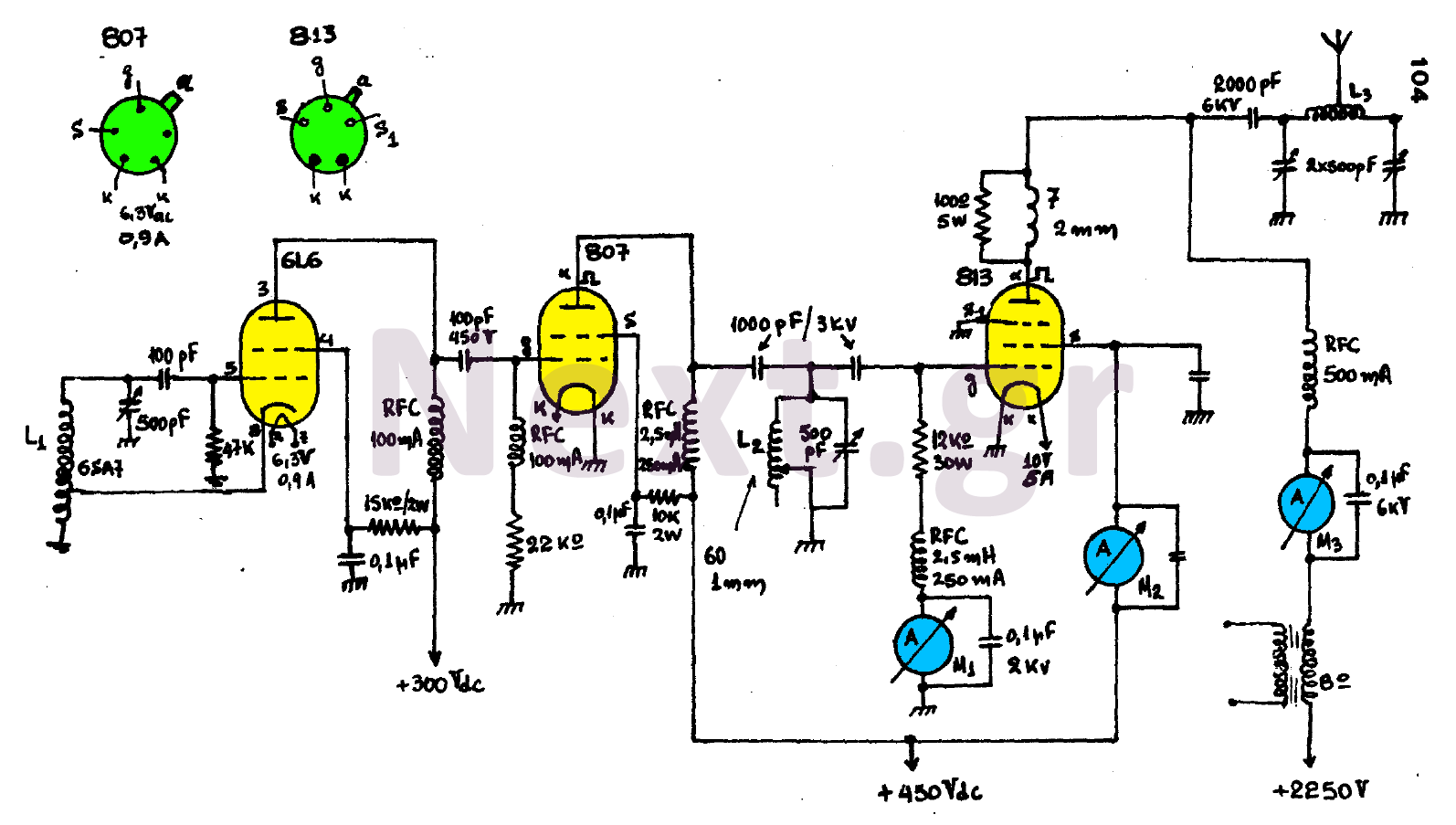
The circuit consists of three main stages and provides the antenna with a power output of 300 watts, contingent upon proper tuning. The first stage is an oscillator featuring an oscillating coil L1, which is commercially available as a...
An Icom PCR-1000 is utilized for listening to various MF, HF, and VHF radio stations. There is a minor inconvenience related to the antennas. The K9AY antenna performs well from 500 KHz to approximately 25 MHz, while the discone...
Simple FM Transmitter Circuit This simple FM transmitter circuit was built using a transistor with a transmission distance of about 300m around your home. The simple FM transmitter circuit utilizes a transistor to modulate audio signals onto a radio frequency...
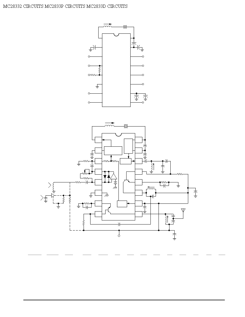
Crystal X1 operates in fundamental mode and is calibrated for parallel resonance with a load capacitance of 32 pF. The final output frequency is produced through frequency multiplication within the MC2833 integrated circuit (IC). The RF output buffer at...
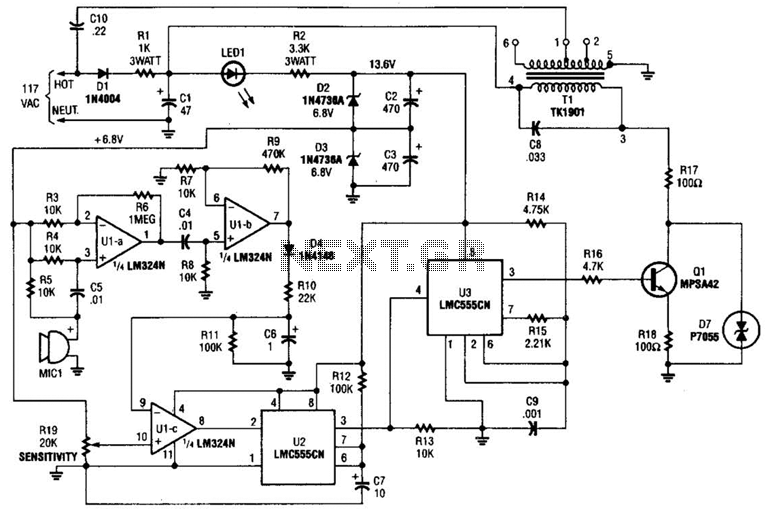
The baby-alert transmitter is constructed using an LM324 quad operational amplifier (U1), two LMC555CM CMOS oscillator/timers (U2 and U3), along with several supporting components. The transmitter activates upon detecting sound at MIC1, emitting a signal. Its operational frequency is...
A high-performance RF amplifier designed for the entire VHF broadcast and PMR band (100-175 MHz) that can be constructed without the need for specialized test equipment. The grounded-gate configuration offers inherent stability without requiring neutralization, provided that appropriate PCB...