
equalizer circuit
The described electrical circuit is a critical component in power systems where multiple generators operate in parallel. Its primary function is to facilitate equitable load sharing among the generators, thereby enhancing system stability and reliability. The circuit architecture incorporates an equalizing coil and a voltage coil within each generator's regulator. The equalizing coil plays a pivotal role in modulating the output of the voltage coil based on the operational conditions of the generator.
When the generators are connected in parallel, any slight variation in voltage levels can lead to uneven load distribution. The equalizing coil acts to either amplify or diminish the voltage coil's effect, promoting a balanced load sharing. This is essential because if one generator operates at a higher voltage, it will naturally take on a larger share of the load, which can lead to overheating or damage if not properly managed.
The equalizing bus serves as a central hub, interlinking all equalizing circuits, ensuring that any adjustments made by one generator are communicated throughout the system. This interconnectedness is crucial for maintaining synchronization and operational harmony among the generators.
Moreover, the inclusion of a low-resistance shunt in the ground lead of each generator is vital. This shunt creates a controlled potential difference between the negative terminals of the generators, which is necessary for the equalizing process. The design ensures a stable potential difference of 0.5 volts at maximum load, which is instrumental in achieving the desired load sharing effect. The low resistance of the shunt minimizes power losses and enhances the overall efficiency of the parallel generator operation.
In summary, the circuit's design elements—equalizing coils, voltage coils, equalizing bus, and low-resistance shunts—work synergistically to maintain balanced load distribution among parallel generators, thereby ensuring optimal performance and longevity of the equipment in a power system.An electrical circuit that ensures that when two or more generators are connected in parallel to a power system they share the load equally. In this arrangement, if the voltage of one generator is slightly higher than that of the other generator in parallel, that generator will assume the greater part of the load.
Such a circuit includes an equali zing coil wound with a voltage coil in each of the regulators, an equalizing bus to which all equalizing circuits are connected, and a low-resistance shunt in the ground lead of each generator. The equalizing coil will either strengthen or weaken the effect of the voltage coil, depending upon the direction.
The low-resistance shunt in the ground lead of each generator causes a difference of potential between the negative terminals of the generators. The value of the shunt ensures a potential difference of 0. 5 volt across it at the maximum generator load. 🔗 External reference
Related Circuits
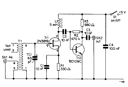
This simple aerial booster circuit design could serve as an alternative or a hobby project for creating an aerial booster device for Citizen Band (CB) radio. The aerial booster circuit is designed to enhance the performance of Citizen Band (CB)...
This circuit is not entirely new, but it is straightforward, dependable, robust, and short-proof. It offers variable voltage up to 24V and adjustable current limiting up to 2A. Customization to meet specific requirements is possible, as detailed in the...
This DC drill speed controller circuit allows for the adjustment of the rotational speed of a drilling machine. A mini-drill machine is always... This circuit utilizes a pulse-width modulation (PWM) technique to control the speed of a DC motor, which...
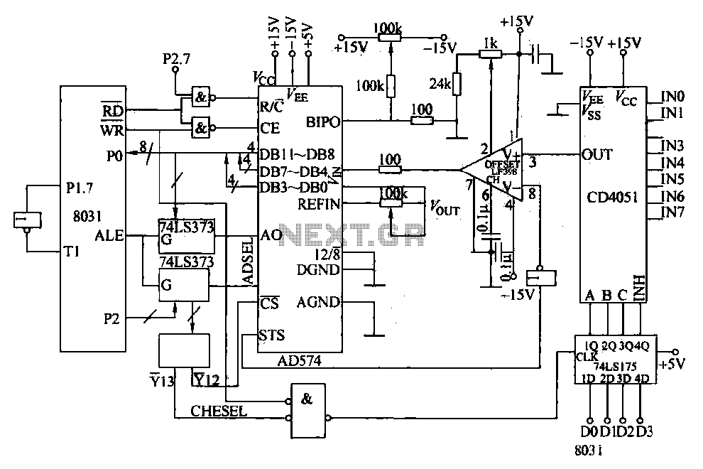
Converters and data sampling: A 12-bit A/D converter, AD574, is interfaced with an 8031 microcontroller circuit. Parameters are measured by a multi-way switch after a CD4051 strobe signal is sent to the sample/hold input device. The selection of the...
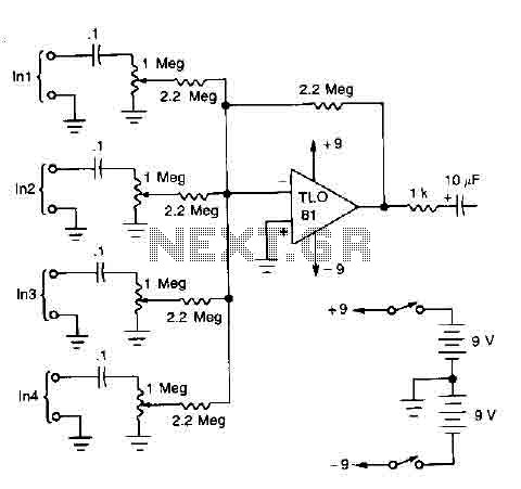
A TL081 operational amplifier is utilized as a high impedance to low impedance converter and as a signal mixer. The input impedance is approximately 1 megohm, while the output impedance is around 1 kohm. The circuit is powered by...
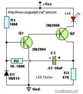
This circuit is designed to flash a high-brightness red LED (5000 mcd), making it suitable for use in fake car alarms or other devices intended to attract attention. The specific values of the components are not critical, allowing for...