
DC Drill Speed Controller Circuit
This circuit utilizes a pulse-width modulation (PWM) technique to control the speed of a DC motor, which is commonly found in mini-drill machines. The primary components of the circuit include a microcontroller or a dedicated PWM controller, a power transistor or MOSFET, a diode for back EMF protection, and a potentiometer for speed adjustment.
The microcontroller generates a PWM signal that varies the duty cycle, effectively controlling the average voltage supplied to the motor. The transistor or MOSFET acts as a switch, turning the motor on and off rapidly based on the PWM signal. The diode is connected in parallel with the motor to protect the circuit from voltage spikes generated when the motor is switched off, a phenomenon known as back electromotive force (back EMF).
The potentiometer allows the user to set the desired speed by varying the resistance in the circuit, which in turn adjusts the PWM signal's duty cycle. This setup provides a smooth and efficient way to control the speed of the drill, enhancing the versatility and usability of the mini-drill machine for various applications.
When designing this circuit, considerations should be made regarding the power ratings of the components to ensure they can handle the operational current and voltage. Additionally, proper heat dissipation methods should be implemented for the transistor or MOSFET to prevent overheating during prolonged use.With the help of this DC drill speed controller circuit you can control the number of revolutions of your drilling machine. A mini-drill machine is always.. 🔗 External reference
Related Circuits
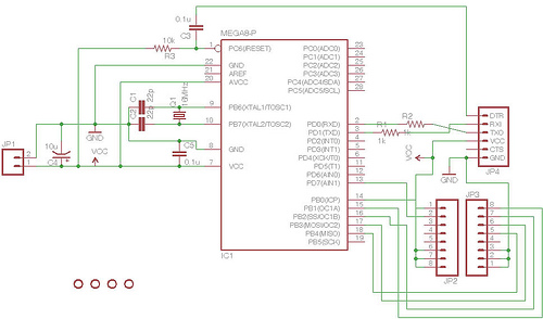
Here is a circuit for using the printer port of a PC for control application using software and some interface hardware. The interface circuit along with the given software can be used with the printer port of any PC...
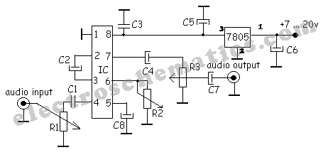
A simple audio compressor is designed using the SSM2165 integrated circuit (IC). There is limited explanation available regarding the schematic of this compressor circuit; however, special attention should be given to the capacitor used. The audio compressor circuit utilizing the...
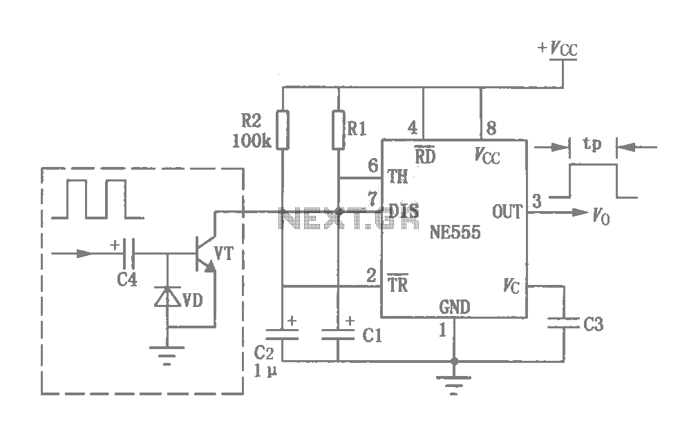
This circuit was originally a type of power-delay control circuit, where the delay time is determined by the timing elements R1 and C1. Additionally, with the inclusion of a "watchdog" circuit, it can be utilized as a monitoring circuit...
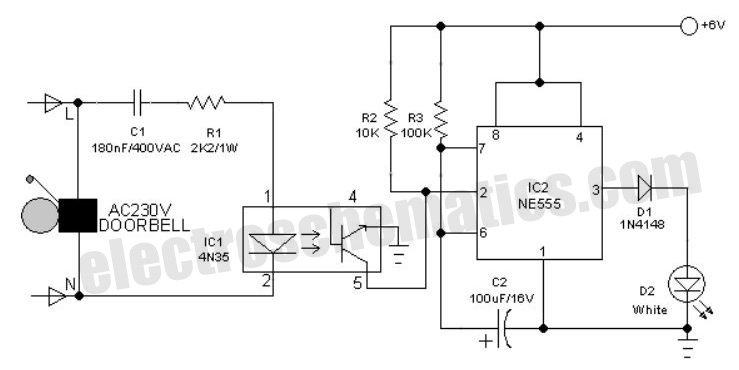
An interesting hobby circuit of a crank doorbell. The circuit is built around a 555 timer and a musical piezo buzzer. It operates using a 9-volt battery supply; a single 9-volt PP3/6F22 compact battery is sufficient to power the...
This text assumes some prior knowledge of PCB etching methods and recounts an experience with the toner transfer technique. For those unfamiliar with the method, additional research may be necessary. The process of constructing a circuit on protoboard is...
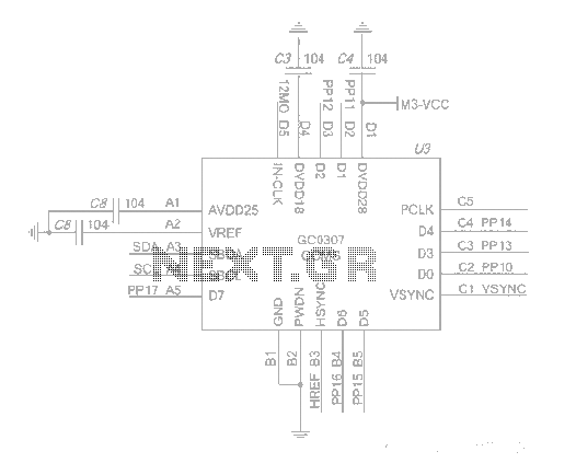
The system employs an optical fingerprint sensor utilizing the ARM Cortex M3 core, specifically the STMicroelectronics 32-bit high-performance microcontroller STM32F205RE. It incorporates a function body composition that utilizes the Sobel edge detection operator, Gabor filtering, image binarization, and various...
Warning: include(partials/cookie-banner.php): Failed to open stream: Permission denied in /var/www/html/nextgr/view-circuit.php on line 713
Warning: include(): Failed opening 'partials/cookie-banner.php' for inclusion (include_path='.:/usr/share/php') in /var/www/html/nextgr/view-circuit.php on line 713