
LED Flasher 2-Transistors circuit diagram

This circuit utilizes a high-brightness red LED, which is critical for visibility in applications such as alarms. The design allows for flexibility in component selection, particularly in the resistors used, enabling the circuit to be adapted based on available materials. The resistor R3 is essential for controlling the LED's brightness; a value of 470 ohms is standard, but a lower value such as 390 ohms can be used to increase brightness at the cost of higher current draw.
The timing characteristics of the flashing LED are determined by the combination of resistor R2 and capacitor C1. The time constant, defined as τ = R2 * C1, dictates how long the LED remains on and off, with the overall flashing frequency being approximately 1/(3*τ). This allows for customization of the flash rate depending on the desired application.
Transistor Q1 functions as a switch, controlling the operation of Q2, which drives the LED. R1 serves to bias Q1, ensuring that it operates in the correct region of its transfer characteristics. If the circuit does not oscillate as intended, adjustments to R1 or R2 may be necessary to achieve the desired behavior.
Diode D1 plays a critical role in managing the feedback to Q1, ensuring stable operation and allowing for higher duty cycle performance. In scenarios where low power supply voltages are utilized, such as 6 to 9 volts, or when a lower duty cycle is acceptable, D1 can be excluded from the circuit, simplifying the design while maintaining functionality.
Overall, this circuit exemplifies a straightforward yet effective design for creating an attention-grabbing LED flash, suitable for various applications with adjustable parameters to accommodate different LEDs and operational requirements.This circuit will flash a bright or high-brightness red LED (5000 mcd). Great for fake car alarm or other awareness getting equipment. Component values aren`t significant, attempt anything else first from the junkbox. Obviously, the 470 ohm resistor (R3) determines the LED`s brightness and limits the current flow to around 20mA. R3 value of 390 ohm can also be implemented as a save value. If you determine to go with a green or yellow led, which take extra current, you might wish to change the 470 ohm with an proper value. Flash rate is determined by R2 and C1 and it is approximately three time constants (3*R2*C1). R1 provides bias to Q1 which should be low enough not to saturate Q2 with the capacitor disconnected.
When the circuit does not oscillate, R1 may be too low or R2 too high. D1 allows for higher duty cycle operation and limits the feedback at the base of Q1 to -0. 7 volts. D1 might be ommited for low supply power like 6 9V and low duy cycle operation. 🔗 External reference
Related Circuits
The circuit was designed to obtain signals through amplitude modulation, exhibiting good sensitivity and selectivity. Amplitude modulation. The amplitude modulation (AM) circuit is engineered to effectively capture and process radio frequency signals. The design focuses on achieving high sensitivity, allowing...
The circuit operates by using a clock signal to drive four D-flip-flops in the control section, which store the on/off state of each current direction for the two stepper motor coils. The flip-flops create a finite state machine (FSM)...
This is a successful vacuum tube project featuring a small amplifier where a 6V6GT output pentode is connected in triode mode, producing an output of approximately 4.5 watts. The project includes a single-ended audio amplifier with a resistive input...
You can play this game alone or with your friends. The circuit comprises a timer IC, two decade counters and a display driver along with a 7-segment display. The game is simple. As stated above, it is a scoring...
DC Motor Control Using a Single Switch. This simple circuit allows for the operation of a DC motor in both clockwise and counterclockwise directions, as well as stopping it using a single switch. The circuit utilizes non-latching push button...
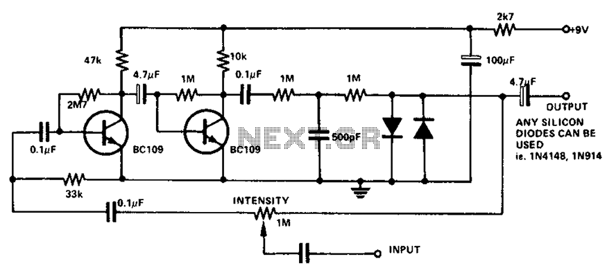
The circuit utilizes a transistor to amplify the input signal. Two diodes are employed to clamp the distorted output, while a 500 pF capacitor filters out high-frequency noise. Under normal conditions, a 1M slide rheostat is used to adjust...