
Ethernet remote device controller sensor circuit
The circuit utilizes the ENC28J60 Ethernet controller, which provides a robust interface for network communications. The microcontroller, an Atmega88, is programmed to handle UDP packets, allowing for efficient command transmission and relay control. The design focuses on a half-duplex communication mode, which is suitable for applications with low traffic, thereby optimizing performance and minimizing the complexity of the circuit.
The inclusion of LED-B serves as an indicator of the operational status of the ENC28J60. Correct polarity is essential for proper functionality, as incorrect connections could lead to malfunction. The relay, connected through CONN3, is driven by the microcontroller's GPIO pin, enabling it to switch on or off based on received commands.
Diode D1 is a critical component in this circuit. It is placed in parallel with the relay coil and is oriented to allow current to flow in the reverse direction when the relay is deactivated. This action prevents voltage spikes, known as back EMF, which can occur when the relay coil is de-energized. Such spikes could potentially damage the microcontroller or other sensitive components within the circuit.
Overall, the design is aimed at providing a reliable and efficient means of controlling a relay through network commands, with considerations for both hardware protection and software efficiency. Future enhancements, such as TCP implementation, could further expand the functionality of this device, allowing for more versatile control options, including web-based interfaces.The main purpose is to show here the circuit diagram and explain the software. We use a UDP application to send commands to the microcontroller. Those commands will then cause the microcontroller to switch on or off the relay. It think it will be possible to even implement TCP. The current UDP software is less than 3k bytes and that is not even half of the memory on an Atmega88. TCP would then allow us to control the device via a web browser. I have however not tried it yet. Here is the circuit diagram. Most of it is very straight forward and standard for the ENC28J60. The polarity of LED-B is important as it determines the duplex operation of the chip. Standard Half-duplex is what makes most sense for a device which will send and receive only rather little traffic. A relay can be connected to connector CONN3. Note the diode D1. It is not useless and it is not the wrong way round in the circuit diagram even though it looks like that.
It is there for those who plan to connect a small 6V relay on that output. It protects the whole circuit against the possibly very high voltages which can be induced by the coil of a relay. 🔗 External reference
Related Circuits
This general-purpose amplifier has a bandwidth of approximately 20 MHz and it uses an LM733/NE592 video amplifier integrated circuit. This circuit can be utilized as a line driver or as a LAN line driver. The circuit employs the LM733/NE592 video...
This operational amplifier (opamp) is available at a low cost. The AD8099 is a very fast opamp with a slew rate of 1600 V/µs and features high-impedance inputs with low input capacitance. Its bandwidth is sufficiently large that at...
This controller consists of three pairs of LED sensors arranged in a 3G-bridge configuration. The driver is capable of operating three actuators, with the motors connected in a Delta configuration. The apexes of the delta are linked to the...
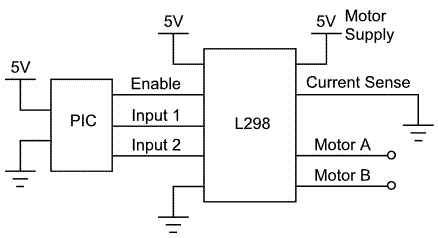
This article demonstrates how to control a DC motor using an H-bridge driver chip with PWM output from a PIC microcontroller for speed control. While a PIC microcontroller is utilized, other controllers such as AVRs, Basic Stamps, and certain...
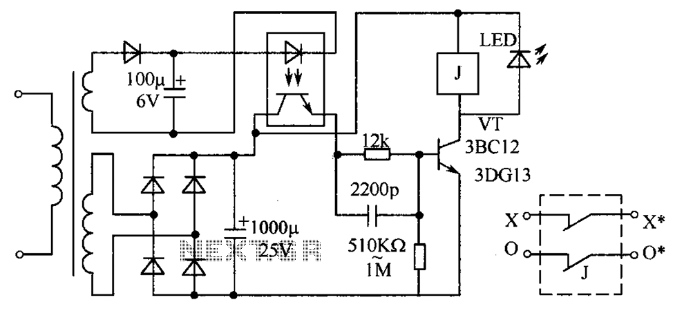
The circuit protection mechanism utilizes optocouplers for on-off control. Under normal voltage conditions, the output from the optocouplers is minimal, and the VT transistor operates in reverse bias. However, if the circuit voltage increases due to reasons such as...
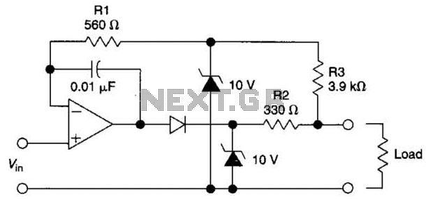
The circuit is designed to drive an external load. A fault condition in the external load circuit could feed excessive current or voltage back into the line drive circuit. If excessive voltage appears from the load, the two zener...