
Actuator circuit
The electronic schematic for this controller involves several key components and configurations. The three pairs of LED sensors are connected to a microcontroller that interprets their signals. Each LED sensor is paired with a corresponding SCR (Silicon Controlled Rectifier), which allows for controlled triggering of the actuators. The microcontroller processes the LED sensor inputs, determining which LED is illuminated and activating the appropriate SCRs to drive the actuators accordingly.
The Delta configuration of the motors is critical for the mechanical movement of the shadow mask. The apex connections to the half-bridges facilitate the necessary control over the motor direction and speed, ensuring that the movement is smooth and precise. The implementation of U-joints at strategic points in the mechanism allows for flexibility while preventing tipping, thereby maintaining the stability of the system.
The integration of temperature control into the LED3 solar tracker presents additional complexity. The temperature sensor circuit connects to the microcontroller, providing feedback on the internal temperature of the solar cooker. The microcontroller can then adjust the position of the shadow mask based on the temperature readings, moving it off-axis as needed to prevent overheating. The use of a high-temperature diode sensor ensures reliable operation under conditions that exceed typical semiconductor limits.
Overall, the design emphasizes robustness and adaptability, enabling the controller to function effectively in various environmental conditions while maintaining operational integrity. The careful selection of components, such as the Tamiya Twin-motor gear box and high gear ratio motors, ensures that the system can handle the required mechanical loads while providing accurate control over the solar tracking process.This controller is essentially 3 pairs of LED sensors in a 3G -bridge configuration. The driver is capable of operating 3 actuators. The motors are connected in a Delta configuration. The apexes of the delta are connected to the center connection of each half-bridge. Of course only 2 actuators are required as the third is stationary and fixed. Whe n a pair of LEDs turns on the associated top SCR the bottom SCRs of the other half bridges is turned on and movement of the shadow mask is toward this LED. If 2 or more LED turn on conditions occur multiple SCRs in both the top and bottom will fire. In many circuits this would be a disastrous condition, however, in this circuit the only thing that happens is there is no movement and the storage capacitor is discharged.
Actually this condition won`t happen in normal circumstances when the light is bright. The LED sensors are arranged in a circle of 6 with a shadow mask sized to exactly illuminate each LED 50%. They are connected in pairs at opposite sides of the circle. A picture is worth way more than a thousand words. As US4798949 and US3945015 teaches us that a U-joint keeps the mirror from tipping I have a rigidly mounted U-joint at the top.
The other U-joints could be ball joints if one can find ball joints that can take high angles. US4798949 needs the other 4 U-joints because of the use of linear actuators. These generally require that the far end be prevented from rotating. The U-joint solved this problem for him. But technically, only the single lower U-joint prevents the mirror from tipping. I worked out a method where I can eliminate the need for limit switches in the actuator. If a crank is used the motion can`t run into the end and jam as in a linear actuator. The protection limit switches can be eliminated. My model uses a Tamiya Twin-motor gear box model 70097. A. Nothing bad happens. The controller just continues to move the crank in the same direction, (the control action is reversed), until the crank is back on bottom and normal control is resumed. DCB asked an interesting question. He was wondering if I could add a temperature control feature to the LED3 solar tracker. He wants to use the tracker to run a solar cooker. He said that with a dish concentrator the temperature in the oven can get to high. He suggested an input to the tracker could move it off axis to control the temperature. I have bread boarded a couple of circuits to try this. I also will try a thermostat version. However, the thermostat seemed kind of high in cost compared to the electronic version. Especially when settings of 350F are needed for baking. I will look at positive temperature coefficient sensors such as platinum or copper types. If a sensor resistance of about 1KOhm were used these could be more rugged than the diode sensors. Each of these circuits is connected to the LED3 5V regulator. The 2 diodes on the left are connected across R2 & R3. Essentially the circuit grounds the LED sensor pairs fooling the tracker into heading for home or park position.
The lower diode is the temperature sensor. It probably should have a glass case to take the temperature. OK, I know 350F is way above the normal operating temperature of semiconductors, but it works in this case. You will need to mount the sensor inside the oven and make connections with high temperature wire. I have some 30 gauge twisted pair wire wrap wire that has Kynar, ( sp), insulation. I twisted and crimped this to the diode to make a good mechanical connection. I also added solder. The solder may melt but still makes a good electrical contact. 1. A motor, a gearmotor with a fairly high gear ratio, either in the motor gearbox or external. I like total gear ratios of 100, 000/1 or more would be nice. In the Small Power System version this has a rubber tired wheel which is able to turn the base of the cooker.
In this example the motor is mounted on the West side. 2. A small 🔗 External reference
Related Circuits
When the unit is positioned near a live conductor, whether insulated or buried in plaster, capacitive coupling occurs between the live conductor and the probe. This interaction activates the counter, resulting in the LED flashing five times per second,...
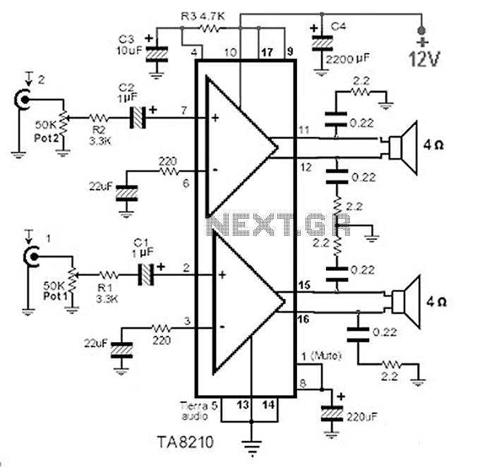
This circuit consists of a 2 x 22 watt BTL amplifier utilizing the IC TA8210AH. It functions not only as an automobile amplifier but is also suitable for low-frequency sound applications, particularly in high-fidelity audio systems, due to its...
The TDA2030 is a monolithic integrated circuit in a Pentawat® package designed to function as a Class AB audio amplifier. It typically delivers up to 14 watts of output power (with a distortion rate of 0.5%) at 14V with...
This integrated circuit (IC) requires fewer external components, making it simpler for beginners to assemble it on a veroboard. The original circuit was sourced from its datasheet. A slightly modified version of the circuit is presented below. This circuit...
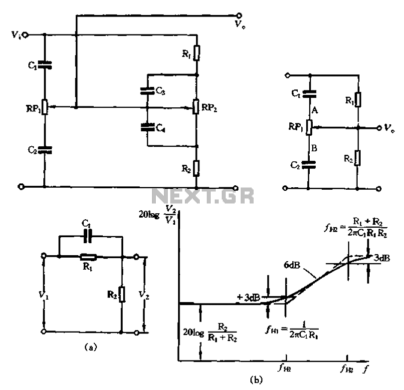
The circuit illustrated in Figure 1-560 represents a treble control potentiometer. Due to the larger capacitance values of C3 and C4 compared to C1 and C2, high-frequency signals can treat C4 as a short circuit. Consequently, the treble adjustment...
This circuit was built to charge two series lithium cells (3.6 volts each, 1 Amp Hour capacity) installed in a portable transistor radio. The circuit is designed to efficiently charge two lithium-ion cells connected in series. Each cell has a...