
DC Motor Speed Controller
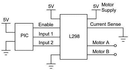
The operation of the H-bridge driver chip is straightforward. The enable pin allows the bridge to be turned on and off, while the input pins determine the direction of voltage across the motor. With the enable pin high and one input pin high while the other is low, the motor will rotate in one direction; reversing the input states will cause the motor to turn in the opposite direction. If both input pins are at the same level while the enable pin is high, the motor will stall (or brake). When the enable pin is low, the motor will freewheel.
Current sense pins are available to detect stalling and excessive current consumption when a resistor is connected to ground. The voltage across the resistor can be calculated using Ohm’s law (V=IR), allowing the current (I) to be determined with a known resistance (R). It is crucial to select a resistor with an appropriate power rating (P = I²R) to handle the stall current of the motors. For instance, with a stall current of 2A, a 1-ohm resistor would dissipate 4W, while a 0.1-ohm resistor would dissipate 0.4W. If current sensing is not required, these pins can simply be connected to ground.
The driver requires two voltage inputs: a logic supply of +5V and a motor supply of less than 46V, which powers the motors. The ground connections for both supplies should be linked. Additionally, diodes must be incorporated to protect against back EMF, which can damage the circuit. Each motor terminal should have two high-voltage/current diodes installed in reverse bias; one diode should connect the negative side to the positive supply, while the other connects the positive side to ground.
For speed control, an initial approach involved applying a PWM signal to the enable pin, intending to rapidly turn the motors on and off, resulting in an average voltage across the motors. Experimental results indicated that the ground reference was unstable due to the characteristics of the transistors in the driver, with one channel displaying a +5V to 0V PWM signal. The other channel, however, did not reach 0V during the off periods of the PWM signal, indicating that the motor was in freewheel mode. This phenomenon results in less precise speed control, resembling a vehicle coasting rather than maintaining a consistent speed. Consequently, even with a 50% duty cycle, the actual motor speed does not equate to half of the maximum speed.
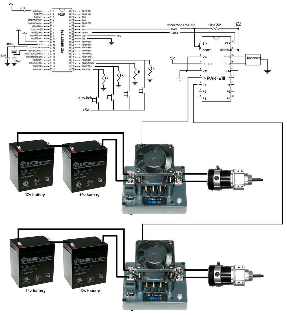
To enhance speed control accuracy, a more refined circuit configuration is necessary, ensuring that the PWM signal effectively regulates motor operation while minimizing the effects of back EMF and providing stable ground references.This article aims to show you how to control a DC motor though an H-bridge driver chip using the PWM output from a PIC to achieve speed control. Although I am using a PIC microcontroller other controllers such as AVR`s, Basic Stamps and certain Picaxe`s can be used.
Before we get too far along; PWM stands for pulse width modulation. For a given fr equency the logic level of the output from the pic will be high (or on) for a certain percentage (duty) of the period (1/frequency in seconds). So with a duty of 50% the PWM signal would be high for 50% of the time. This can be used to create average voltages (i. e. with a PWM signal at 5V half of the time and 0V the rest the average voltage would be 2. 5V), by varying the voltage to the motors you can control the speed of the motor! The operation of the H-Bridge driver chip is fairly simple. With the enable pin you can turn the bridge on and off, the input pins you can change the direction of the voltage across the motor.
So with the enable high and one input pin high and one low the motor will turn one way and with them the other way round the motor will go in the opposite direction. If they are both at the same level the and the enable is high then the motor will stall (or break) and with the enable low the motors will freewheel.
There are also current sense pins which can be used to identify stalling and excessive current consumption when a resistor is connected to GND, and the voltage across the resistor will be follow V=IR so with a known R the current I can be found. The power rating of the resistor is very important, P = I 2*R so you must make sure your resistor can handle the stall current of your motors.
The ones I am currently work with are rated at 2A stall current, making 4W with a 1Ohm Resistor or 0. 4W with a 0. 1Ohm resistor. But if you do not need this, just connect these pins to GND and all will be fine! There are 2 voltage inputs for the driver, logic and motor supply. Logic should be +5V and supply should be < 46V and will be the voltage supplied to the motors. The GND of both supplies should be connected. One other VERY IMPORTANT set of components that need to be added are the diodes to protect against back EMF which can damage your circuit.
Basically on each motor terminal 2 high voltage / current diodes should be placed with reverse bias. So on each terminal there should be a diode with the negative side connected to the +ive supply and one with the +ive side connected to the GND. (please see the datasheets for more detailed info). And here is a quick pic of the motors I used, erm, motors and resistor! The small motor is the expensive maxon and the larger one is a cheapo from a old toy RC. Ok so speed control. My first attempt used the following system. I used a PWM signal on the enable pin, the idea was that the PWM would in affect turn the motors on and off very fast resulting in a average voltage across the motors.
Here is a scope image when using a 100Ohm resistor in place of a motor (there is no back emf or noise to worry about). It is as I expected, the GND is not constant due to the characteristics of the transistors in the driver and one channel shows a +5V to 0V PWM signal.
As you can see the GND channel is okay, but the other channel never goes to 0V. This is because the PWM signal is off in these periods, according to the truth table in the datasheet this means that the motor will be in freewheel mode. This would be a iron core passing through a magnetic field, so a voltage will be induced, this is what is being shown here.
This means that speed control is not very accurate, as it would be more akin to a car coasting than the car going a distance then stopping then going a distance again. So even if the duty is 50% the actual motor speed will not be 50% of full speed. Using this circuit much more control over speed is possible. To start with the enab 🔗 External reference
Related Circuits
The artwork style of the operational amplifier and the meter face suggests that it is an ACC design from an old issue of ACC Notes. The second image was scanned, and the text below was written from scratch. If...
A very simple controller circuit with impressive performance. If a fully automatic computer-controlled rotator is not affordable but enhanced capability is desired from a basic rotator, the ZL1BPU Rotator Controller offers a simple "point and shoot" computer-controlled antenna solution....
Build a large dancing robot. This was intended to be a walking robot, but it ended up moving in a more rhythmic manner. A video is available in the last step. The project involves the construction of a large dancing...
Previously, one magnet measured 2x2x3 cm; it has now been replaced with a round magnet measuring 1.5 x 2 cm. This change significantly impacts the motor's operation, allowing it to run on 1 V and 0.1 A, resulting in...
Typically, a charged lead-acid battery and a power inverter are utilized to ensure a well-organized holiday where family members can enjoy their electric and electronic devices. With rechargeable lead-acid batteries, it is often beneficial, if not essential, to determine...
The 0.1µF monolithic capacitors will be marked '103 K' and the 15pF monolithic capacitors are marked '15 J'. It is crucial not to confuse the two. Do not remove either the MOSFETs or the integrated circuits from their protective...
Warning: include(partials/cookie-banner.php): Failed to open stream: Permission denied in /var/www/html/nextgr/view-circuit.php on line 713
Warning: include(): Failed opening 'partials/cookie-banner.php' for inclusion (include_path='.:/usr/share/php') in /var/www/html/nextgr/view-circuit.php on line 713