
Fade one lamp dimming switch circuit
The fade-in fade-out light switch circuit is designed to create a smooth transition in lamp brightness, enhancing the user experience and providing a gentle lighting effect. The circuit typically consists of a power supply, a switch (SA), a potentiometer (RP), and components such as resistors (Rs), capacitors (cl), and possibly a thyristor for controlling higher current loads.
When the switch SA is engaged, the circuit allows current to flow, charging the capacitor cl through the resistor Rs. This charging process creates a time delay, during which the voltage across the capacitor increases gradually. As the voltage rises, the lamp connected to the circuit experiences a corresponding increase in brightness, providing a smooth fade-in effect. The rate of brightness increase can be adjusted by changing the values of Rs and cl, which determine the time constant of the circuit.
Upon opening the switch SA, the capacitor begins to discharge, causing the lamp brightness to decrease gradually. The discharge rate is also influenced by the values of Rs and the potentiometer RP, allowing for fine-tuning of the fade-out duration. The design ensures that the transition between the two states is not abrupt, thereby creating a pleasant visual effect.
For applications requiring control over multiple lamps or higher wattage lighting, the circuit can incorporate a high-current rectifier diode to handle the increased load. Additionally, a thyristor can be utilized to provide more robust control over the power delivered to the lamps, ensuring reliable operation under varying conditions.
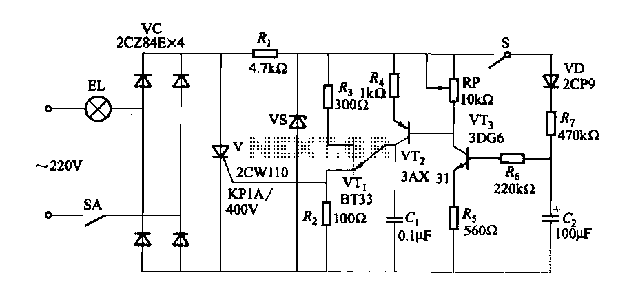
Overall, this circuit design provides a versatile solution for controlling lamp brightness with smooth transitions, suitable for various lighting applications in residential and commercial settings.Fade-in fade-out light switch can turn on and off when the lamp brightness changes slowly, and the brightness can be adjusted. (1) One of fade-dimming lamp switch circuit circu it shown in Figure 2-35. When closing the switch SA, the lamp brightness from weak to strong light; open the switch SA, lamp brightness from strong to weak extinguished. Adjustment potentiometer RP, can change the bulb. Such as using the values shown in Figure 2-35, lights fade in, fade-out process of approximately 60s.
Change Rs, horses, cl, and the resistance of RP, you can adjust the fade in, fade-out time. If you want to control the lamp power group, select high current rectifier diode and thyristor can be.
Related Circuits
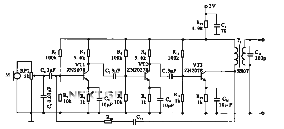
This circuit is a recording signal amplifying transistor circuit that illustrates the functioning of a microphone signal amplifier. After adjustment through potentiometer RP1, the signal is applied to the transistor VT1, which operates as a common emitter amplifier. The...
Free energy motors and generators are available for purchase, featuring plans for overunity devices. These devices resemble oscillators used in Joule thief circuits, although there may be some errors present in the designs. However, the concept remains clear. Free energy...
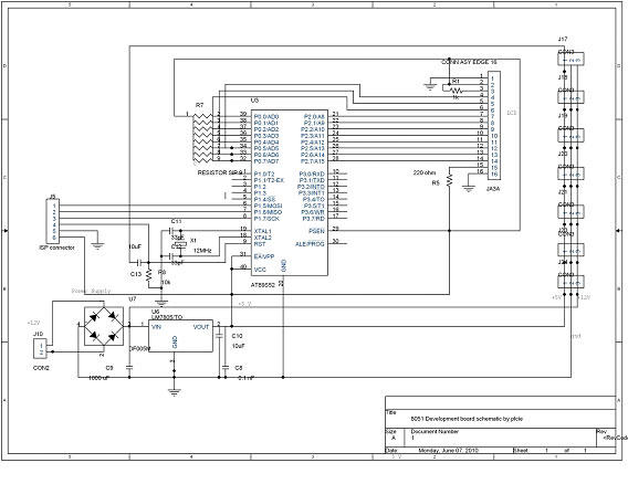
DTMF-based Robo Car design using the 8051 microcontroller project. This project demonstrates a method to control a domestic system using the DTMF tone generated by a telephone instrument when the user presses the keypad buttons of a mobile phone...

This circuit design was used to switch on device via a LED photocell arrangement (optocoupler) using components R1, C1, D1 and Q1. It produces a delay on powering up to ensure correct sequencing of certain equipment. A very simple...
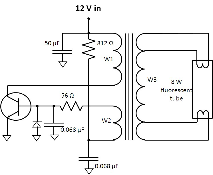
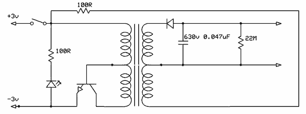
A fluorescent lamp has specific requirements for startup and continuous illumination. The flyback converter is designed to meet these requirements. Initially, attempts to locate a schematic for the fluorescent lamp assembly proved unsuccessful. However, the low parts count and...
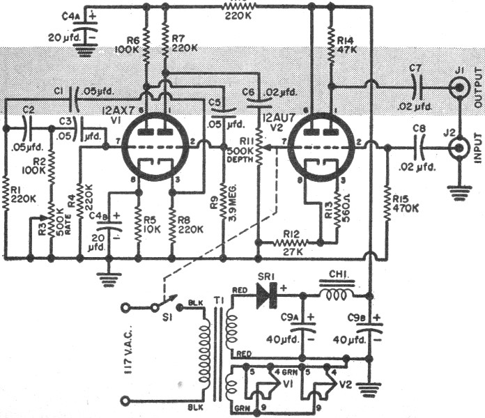
RF Cafe visitor Jim L. requested that this "Build Your Own Vibrato" article from the December 1957 edition of Popular Electronics be posted. The tagline states, "Make like Elvis with an electronic throbbing guitar." Vibrato, for those unfamiliar with...