
Recording signal amplifying transistor circuit
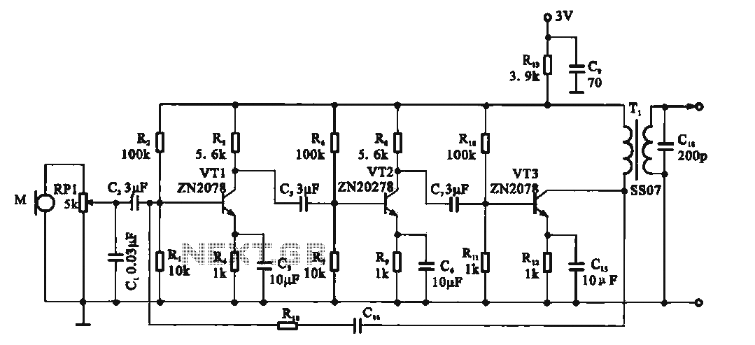
The recording signal amplifying circuit is designed to effectively capture and enhance audio signals from a microphone. The use of a common emitter configuration for transistor VT1 allows for significant amplification of the input audio signal. The adjustment via potentiometer RP1 provides flexibility in tuning the gain to accommodate various microphone sensitivities and recording conditions.
The negative feedback resistor connected to the emitter of VT1 plays a crucial role in stabilizing the DC operating point, ensuring consistent performance across different operating temperatures and signal conditions. Capacitor C3 acts as a decoupling element, which is essential for filtering out noise and preventing oscillations that could degrade the quality of the amplified signal.
Transformer T is pivotal in this circuit, as it not only couples the amplified audio signal to the recording head but also serves to match impedance between the amplifier and the recording device. The secondary winding of the transformer, in conjunction with the 200 pF capacitor, is specifically designed to boost high-frequency response, addressing the common issue of high-frequency signal loss during the recording process.
The feedback network involving capacitor C16 and transistor TV1 is instrumental in refining the frequency response of the amplifier. This feedback mechanism allows for better control over the amplifier's gain across a range of frequencies, ensuring that the output remains clear and defined even at higher frequencies.
The circuit's design also emphasizes low power consumption, making it suitable for battery-operated devices. The use of a 3V power supply derived from two batteries allows for extended operation without frequent replacements, which is particularly advantageous in portable recording applications. This combination of features makes the recording signal amplifying transistor circuit a robust solution for high-quality audio recording tasks.Recording signal amplifying transistor circuit Shows the recording signal transistor amplifier, the microphone signal after adjustment by potentiometer RP1 applied to the transistor VT1, it is a common emitter amplifier, where VT1 emitter connected to the current negative feedback resistor as a stable DC operating point, C3 to decoupling capacitor so that VT1 exchange gain increase, the audio signal after amplification levels applied to the transformer T, the primary winding. By transformer coupled audio signal to the recording head for recording. Transformer secondary winding and 200 pF capacitor in parallel to enhance the high-frequency signal, the recording process to compensate high-frequency losses.
VT3 collector outputs Rcs. C16 TV1 feedback to the base, with spout improve the frequency characteristics of the amplifier. The output of the amplifier with variable pressure mode can compensate for high frequency signals. 3V low voltage power supply circuit by the use of two batteries, and has a low power consumption characteristics.
Related Circuits
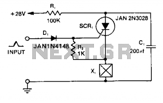
Capacitor C1 is charged to +28 V through resistor R1 and stores energy for firing the squib. A positive pulse of 1 mA applied to the gate of SCR1 will cause it to conduct, discharging C1 into the squib...
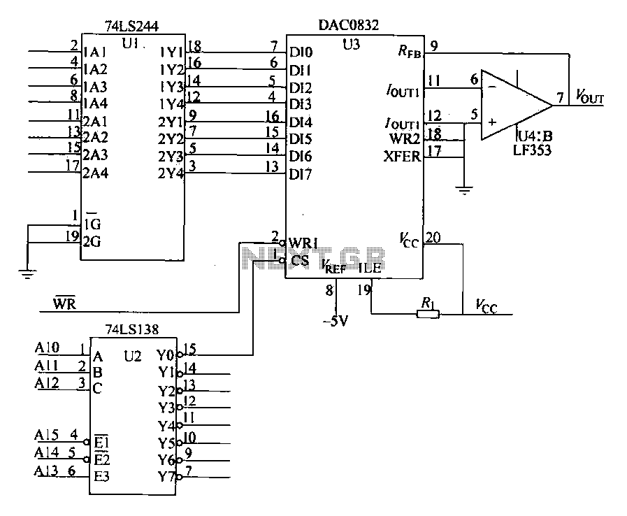
The DAC0832 is depicted in Figure 27-13 as a single-phase circuit connected to the 8086 CPU. The internal 8-bit data input of the DAC0832 must be interfaced with the CPU and the D/A converter interface circuits for data transmission,...

Personal Safes are revolutionary locking storage cases that open with just the touch of your finger. These products are designed as secure storage for medications, jewelry, weapons, documents, and other valuable or potentially harmful items. These utilize fingerprint recognition...
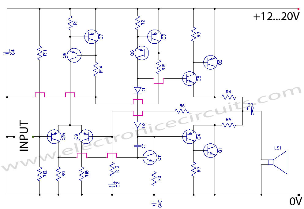
Discrete Class AB Transistor Audio Power Amplifier Circuit Diagram. This is a Class AB transistor power amplifier. It is a simple amplifier to... A Class AB transistor audio power amplifier is designed to provide high-quality amplification for audio signals while...
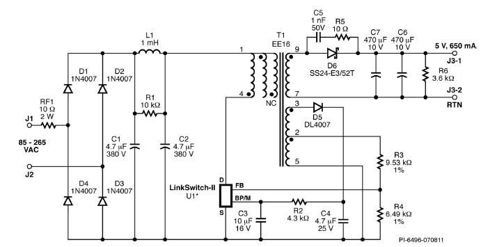
A simple 3.25W constant voltage/constant current (CV/CC) charger can be designed using the LinKSwitch family IC manufactured by Power Integrations. This electronic circuit project is intended to provide a 5-volt output with a maximum current of 650mA. The 3.25W...
In a lithium-ion cell, a voltage of 3.8V per cell indicates a state of charge of approximately 50%. It is important to note that using voltage as a fuel gauge is not precise, as cells manufactured by different companies...
Warning: include(partials/cookie-banner.php): Failed to open stream: Permission denied in /var/www/html/nextgr/view-circuit.php on line 713
Warning: include(): Failed opening 'partials/cookie-banner.php' for inclusion (include_path='.:/usr/share/php') in /var/www/html/nextgr/view-circuit.php on line 713