
Fairy Flashing LED Lights
The circuit operates on a straightforward principle where the flashing LED acts as a pulse generator, creating a square wave signal that drives the base of the NPN transistor. This type of transistor is commonly used in low-power applications and is ideal for switching operations. The resistors in the circuit serve to limit the base current to the NPN transistor, ensuring that it operates within safe parameters while being driven by the oscillating signal from the flashing LED.
When the NPN transistor is turned on, it allows current to flow through the connected string of LEDs, illuminating them. The forward voltage drop across each LED must be considered to ensure that the total voltage drop does not exceed the supply voltage. The alternating flashing effect can be achieved by adding a PNP transistor, which is configured to turn on when the NPN transistor is off, thus creating a complementary flashing pattern between the two LED strings.
In terms of power supply, the use of an unregulated 12 V source is suitable for this circuit, but care must be taken to ensure that the supply voltage does not exceed the maximum ratings of the components used. The absence of a current-limiting resistor in the LED chain simplifies the design, but it requires precise matching of the forward voltage characteristics of the LEDs to avoid overcurrent conditions.
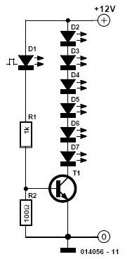
Overall, this circuit provides a versatile and engaging way to create visual effects using LEDs, suitable for various applications beyond just holiday decorations. By experimenting with different LED colors and configurations, users can customize the flashing patterns to suit their preferences, making it a fun and educational project for electronics enthusiasts.This simple and cheap circuit is not just for Christmas! There are just two resistors, a small-signal transistor such as a BC547, one flashing` LED and a string of normal` LEDs. The flashing LED works as an oscillator and switches the transistor on and off; and the transistor switches all the other LEDs.
An (unregulated) 12 V mains supply can be u sed for power. No current-limiting resistor is required in the LED chain, because the forward voltages of the LEDs in the chain add up to the supply voltage. If red LEDs are used, with a voltage drop of 1. 65 V, then 12 V will supply seven; alternatively, use six yellow (2. 1 V each) or five green (2. 7 V). You can of course always mix the colours. Alongside the NPN transistor add a PNP transistor with its emitter connected to +12 V, with another string of LEDs connected down to ground.
The two strings will flash alternately. Be the first of your friends to get free diy electronics projects, circuits diagrams, hacks, mods, gadgets & gizmo automatically each time we publish. Your email address & privacy are safe with us ! 🔗 External reference
Related Circuits

This circuit is a stable frequency counter with an accuracy of 5 significant digits. It operates within a frequency range of 0 to 30 MHz and has an input sensitivity greater than 100 mV. The probe connects to the...
An LED will fail if the current flowing through it is excessively high. This issue can be easily resolved by incorporating a simple resistor in series, which is an effective and low-cost solution. However, as the power supply voltage...

1999 Civic Wiring Diagram for Courtesy Lights Manual PDF. The 1999 Civic Wiring Diagram for courtesy lights provides a comprehensive visual representation of the electrical connections and components associated with the vehicle's interior lighting system. This schematic is essential for...
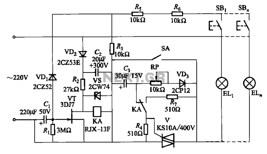
The circuit illustrated in Figure 2-50 utilizes a field effect tube and a combination of electronic components to create a unique self-lighting controller. The working lamp remains illuminated at a reduced brightness rather than being completely turned off, which...

The circuit operates with a 220V mains supply through a diode (VDi) configured as a half-wave rectifier. Capacitors C1 to C3 are charged, and due to the lack of full synchronization in the charging process, a pilot thyristor is...

CAT3606 is a high-efficiency white LED driver. This adjustable charge pump is suitable for general-purpose, large-panel, flicker-free white LED backlighting and dual-display systems. The CAT3606 inductor boost circuit can replace conventional high-brightness backlighting requirements, thereby simplifying system design. It...
Warning: include(partials/cookie-banner.php): Failed to open stream: Permission denied in /var/www/html/nextgr/view-circuit.php on line 713
Warning: include(): Failed opening 'partials/cookie-banner.php' for inclusion (include_path='.:/usr/share/php') in /var/www/html/nextgr/view-circuit.php on line 713