
Stairs Corridor light-controlled circuit
The circuit design employs a field effect transistor (FET) as the primary switching element, which is known for its high input impedance and low power consumption. The self-lighting controller operates by gradually increasing the voltage across the lamp, thereby reducing the inrush current that typically occurs when a lamp is turned on. This gradual increase in brightness not only enhances user comfort but also minimizes thermal stress on the filament, leading to a longer operational life for incandescent bulbs.
The delay mechanism is essential for applications where a constant low-level illumination is desired, such as in hallways or staircases. The time constant, governed by the values of the capacitor (Ci) and resistor (Ri), can be adjusted to suit specific requirements. By selecting different component values, the delay time can be modified, allowing for customization based on the intended use of the lighting system.
In practical applications, the circuit can be integrated into various lighting fixtures, providing automatic dimming capabilities. The switch (SA) serves as a manual override, enabling users to bypass the dimming function and access full brightness when necessary. This feature is particularly useful during cleaning or maintenance tasks, ensuring safety and visibility.
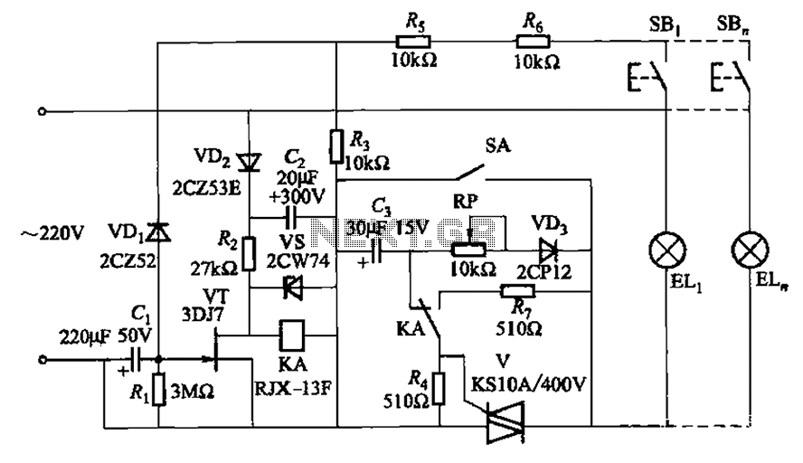
Overall, this self-lighting controller circuit represents an innovative approach to lighting management, combining efficiency with user-friendly operation. Its design principles can be adapted for a wide range of lighting applications, making it a versatile solution in modern electrical engineering. Circuit shown in Figure 2-50. This circuit uses field effect tube should, through the ingenious electronic components constitute a unique self-lighting controller. The informal working lamp illumination is not put out off, but the light is dim. In some cases this is needed. At the same time, this can greatly extend the life of lamps, because before fully lighting the lamp filament has a large cooler state filament resistance, thus avoiding that a large electric lamp connected to the grid when the impact of flow. Delay time is determined by Ci, Ri, as shown by numerical Figure 2-50 about 6min. To disconnect from the controller and enhanced lighting, for example, when cleaning stairs, hit the switch SA may be closed position, then the lamp will add a full-grid voltage.
Related Circuits
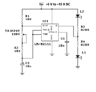
This is a simple LED flasher project that utilizes a common 555 timer integrated circuit (IC) for its operation. It is configured in astable mode, which means its output functions as a square wave oscillator. Two LEDs are connected...
The need for a device that can detect and extinguish a fire on its own is long past due. Many house fires originate when someone is either sleeping or not home. With the invention of such a device, people...

The circuit consists of a sound detection circuit and a monostable trigger circuit that activates a relay. VT1 amplifies the input audio signal. When a signal is detected, the 555 timer is triggered, pulling K. Simultaneously, VT2 conducts, allowing...
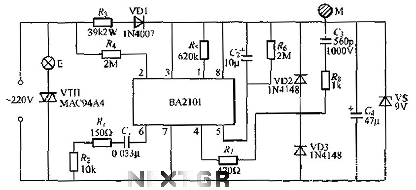
The BA2101 is a dimming controller utilizing an ASIC to create a barrel of light touch stepping. It is a non-constant lamp suitable for heir light. Each touch on the electrode sheet M can adjust the lamp brightness through...
A circuit was required to function as a bass boost. The design was adapted from a circuit by ESP Sound, focusing solely on the frequency range of 35-150 Hz. The bass boost circuit, as adapted from the original design, primarily...

This circuit consists of a temperature sensor, amplifier, voltage-to-frequency (V/F) converter, a three-digit binary coded decimal (BCD) counter, a time base, and seven-segment LED displays. In addition to the 9400 V/F converter, other integrated circuits (ICs) required for this...