
Thrifty LED Protector

The described circuit effectively manages LED current through a combination of resistive and inductive components, ensuring safe operation while maximizing efficiency. The use of a series resistor (R5) provides a simple method for current measurement, while transistor T2 acts as a protective switch that prevents excessive current flow. The inductor L1 plays a critical role in energy storage and release, allowing for a smooth current flow to the LED (D1) when T2 is conducting. This arrangement not only protects the LED from overcurrent conditions but also enhances the overall efficiency of the circuit by utilizing D1 as a free-wheeling diode.
The hysteresis introduced by resistor R6 is essential for stabilizing the operation of the circuit, preventing rapid switching that could lead to increased power loss. The circuit is designed to operate effectively across a range of supply voltages, making it versatile for different applications. The adaptability of the coil value allows for customization based on specific requirements, making it suitable for various LED types.
In summary, this circuit design provides a robust solution for driving LEDs safely while optimizing efficiency, making it ideal for use in battery-powered devices and other applications where power conservation is critical. The careful selection of components and their arrangement within the circuit ensures reliable operation and longevity of the LEDs used.An LED is sure to fail if the current through it is too high. You will soon discover this after you have blown a few up. A simple resistor in series suffices to solve the problem and a better solution is almost inconceivable, because in this case you need only one additional cheap component. As the power supply voltage increases, an increasing amo unt of power is lost in the resistor. In particular with battery-powered equipment it is worthwhile to make a power-saving version, which does require a few more parts however. The circuit shown in the figure has deliberately been designed with parts that everyone will have lying around, except perhaps the small coil.
In nearly all modern switching power supplies there is an attempt to monitor the current. It is generally the case that components will fail if the current or power is too high and this is very effectively avoided with this technique. It works like this. Resistor R5 measures the current through the coil and T2 watches` to make sure it doesn`t become too large.
L1 will never go into saturation, which could cause T3 to give up the ghost. As soon as the current through R5 increases to about 25 mA, T2 will conduct, T1 will block and T3 will also block. The current cannot flow through T3 any more and will look for another path, in this case through LED D1, which will now light up.
By placing D1 in this position it acts in fact as a free-wheeling diode, which is good for the efficiency. As soon as the current drops, T2 will block again and T3 will conduct. R6 provides a small amount of hysteresis so that the switching frequency of about 50 kHz does not become unnecessarily high (which would increase the loss).
The circuit works from about five volts, depending on the forward voltage of the LED. From about 9V you will clearly notice the improvement in efficiency. The circuit is suitable for all types of LEDs, including the blue and white ones that need 3. 5 V. The voltage that is generated by the coil will automatically adapt. The maximum power supply voltage is 24 V. A little clarification regarding the choice of coil: the value is not critical, it could just as easily be 3. 9 mH or 6. 8 mH. Even 10 mH can be used, especially if the power supply voltage is greater than 9 V. The coil does need to be suitable for at least 25 mA. You can usually take a guess based on the physical dimensions of the coil. The coil will have to be at least 15 mm long and have a diameter of 7 mm. Incidentally, there have been great advances regarding coils in the least few years. Modern SMD-coils are much smaller and can nevertheless handle high currents. Unfortunately they are not usually available in values over 1 mH. 🔗 External reference
Related Circuits
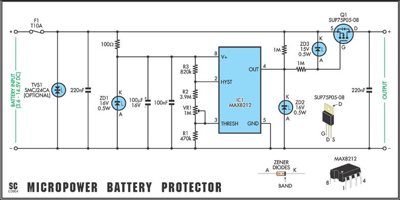
Protect expensive batteries from discharge damage with this mini-sized electronic cutout switch. It consumes minimal power and can be adapted to accommodate a wide range of battery voltages. In May 2002, Silicon Chip introduced the "Battery Guardian," a project...
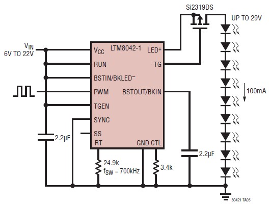
The LTM8042 integrates a boost power topology with a unique current loop to function as a constant-current source. The PWM input allows for LED dimming ratios of up to 3000:1, while analog dimming can be achieved with a single...
This ultra-bright white LED lamp operates on 230V AC with low power consumption. It is suitable for illuminating VU meters, SWR meters, and similar applications. The ultra-bright LEDs available in the market range from Rs 8 to 15. These...
This is a simple design of a single flashlight. This small circuit is within a half hour to build. The circuit operates from 4.5 to 12 V. Of course it is possible other than to drive an LED. More:...
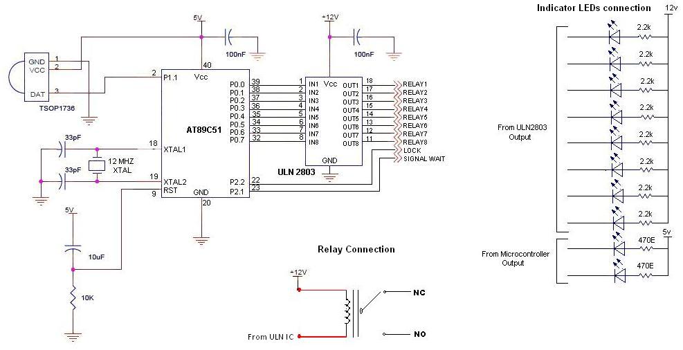
To control multiple switches, it is necessary to transmit several bits via infrared (IR) transmission to indicate which key is pressed on the remote control and, consequently, which switch on the switchboard to operate. This project utilizes a commercially...
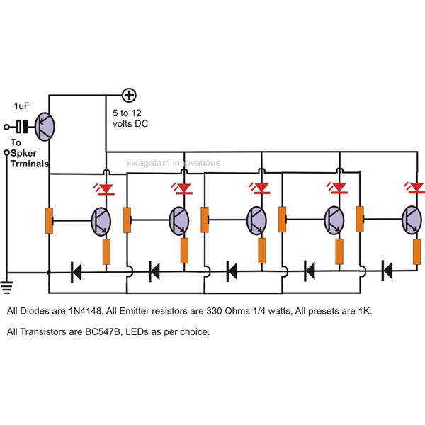
The LEDs in the circuit light up sequentially and "dance" in response to the music level applied at the input, preferably from the speaker terminals of the audio device being monitored. This configuration is consistent across all LEDs in...