
famicom disk system fd3206 write mod
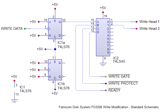
In order to do a successful mod, you`ll need to familiarize yourself with this particular area of the circuit board, since we`ll be cutting a couple of traces and soldering several wires to it. Zoom in on the picture by clicking on it, compare it with your disk drive and make sure you can recognize the basic structures like the two parallel columns of solder points (which by the way is the Drive Controller IC).
There`s no room for error! You`ll need to cut two circuit board traces that link the original disk writing stage with the write head assembly. This will disable the original, crippled disk writing circuitry and allow our custom circuitry to take control.
Cut the marked traces in the exact same place that is detailed on the picture. If you cut them at another place you`ll also disconnect the pull-up resistors from the head assembly, which will prevent proper operation of the disk drive. Once the traces have been severed, use a multimeter or a magnifying glass to make sure that they`ve been completely disconnected from the chip.
Now take your mod board and solder each wire to its corresponding place indicated by the following picture. It helps to use color coded wires to avoid confusion. The following step is optional but highly recommended. Take the bottom metal plate of the drive mechanism and cover the area directly underneath the 3206 chip with significant amounts of electrical tape.
By doing this you`ll prevent possible short circuits between your soldered wires and the bottom metal plate. It also wouldn`t hurt to do the same to the bottom of the mod board, just in case. With the wires firmly soldered into place, put the bottom metal plate back into place and route the wires through the small opening that the plate allows for.
Make sure that the wires aren`t being pinched by the metal plate and screw it back together. Slide the drive mechanism back into the casing, taking care for the mod board. Plug the power board connector into the drive mechanism, and place the mod board on an empty space inside the FDS drive casing, a good place for it should be one of the empty corners at the sides of the drive mechanism, making sure that it doesn`t short circuit with the metal parts of it. Use a piece of tape or a drop of hot glue to secure the board to the case and to avoid rattling. With your FDS drive back together, it`s time to test your newly installed write modification. Hook up the FDS to your Famicom as usual, insert a disk that you don`t care about corrupting (just in case something is wrong), and turn everything on.
The disk drive should work just like before and boot up your game. Depending on the game, play a couple of levels and then lose all your lives, or create a new character/save file in order to call a data save routine. Select the SAVE option or confirm the creation of the new character, and wait for the disk drive to do its thing.
If everything`s correct, the data should be saved successfully. If it does, congratulations! 🔗 External reference
Related Circuits
A proposed solution is being tested to prevent overvoltage from reaching the irreplaceable IC U5 - A1752CF after either the switch drives or returns experience a static electric shock or encounter the 24VDC solenoid bus. The protection mechanism is...
PIC C Compilers are utilized to compile source code, leveraging the extensive built-in functions offered by these compilers. A single C statement can produce multiple pages of PIC RISC instructions, eliminating the need for manual coding. CCS charges $125...
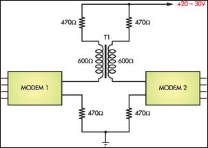
Connecting two PCs via modems using a twisted pair cable may not yield any results because the modems are designed to operate over a phone line. The scenario described involves the attempt to establish a connection between two personal computers...
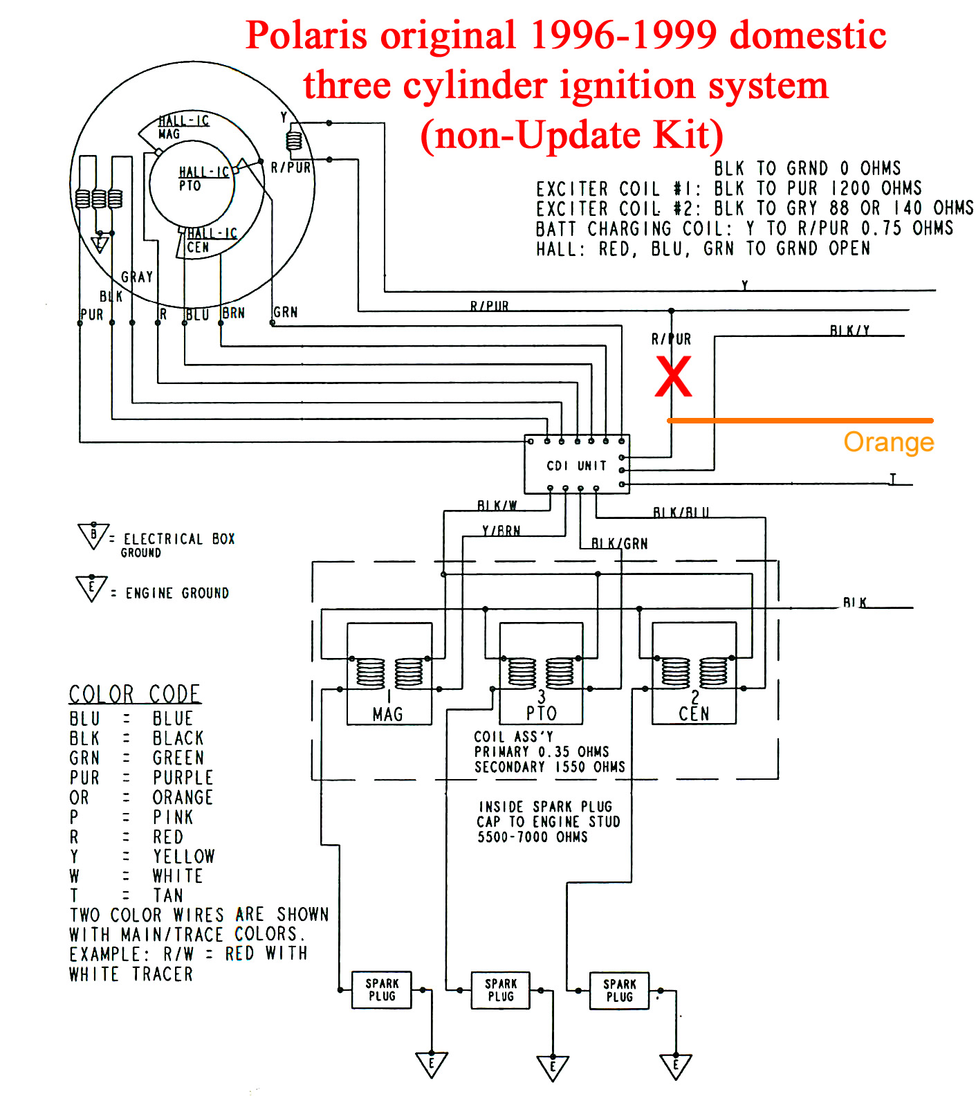
A Polaris Jet Ski Model SLTX 1050 with a 3-cylinder engine from the year 1998 was operational until a piston failure occurred. The engine was removed, rebuilt, and reassembled, but it fails to start due to a lack of...
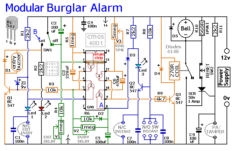
This circuit incorporates automatic exit and entry delays along with a timed bell cut-off feature. It accommodates both normally-closed and normally-open contacts and includes a 24-hour personal attack/tamper zone. The circuit is permanently connected to a 12-volt supply and...
.png)
The one-touch turn signal (OTTS) module enhances the functionality of the turn signal lever by introducing a mode where a single touch activates the indicators to blink for a specified number of times. This feature is commonly referred to...