
One-touch turn signal module
.png)
The OTTS module circuit design incorporates a straightforward yet effective approach to enhance vehicle turn signal functionality. The use of the Atmel ATtiny24 microcontroller allows for programmability and flexibility in operation, facilitating the implementation of the comfort blinker feature. The integration of a low-dropout voltage regulator ensures that the microcontroller operates reliably under varying conditions, which is crucial in automotive applications where voltage fluctuations can occur. The DIP switch S1 provides an intuitive method for users to customize their preferences, making the module user-friendly.
Moreover, the choice of N-channel MOSFETs for the output stage is a deliberate decision aimed at achieving efficient switching capabilities. These components are selected for their ability to handle significant currents while maintaining low resistance, thus minimizing heat generation and enhancing overall system reliability. The design also accounts for the challenges associated with accessing indicator signals within the vehicle, ensuring that the module can be installed in various vehicle configurations without compromising performance.
In summary, the OTTS module represents a well-engineered solution for modern vehicles, merging functionality with user convenience. Its design considerations reflect an understanding of both the electrical environment of automotive systems and the needs of end-users, making it a valuable addition to any vehicle's signaling system.The one-touch turn signal (OTTS) module enhances the functionality of the turn signal lever by adding a mode where a single touch makes the indicators blink for a certain number of times. This behavior is also known as lane change turn signal or comfort blinker. This sub-article describes one of the variants of the OTTS module, the NN version. Thi s variant is for electrical systems where the shared contact of the turn signal lever switch is connected to the negative terminal and the flasher relay switches the turn signal lamps between lamp and negative terminal. For more information about the OTTS module or other variants refer to the one-touch turn signal module main article.
As is the case with many microcontroller based projects the circuit diagram is rather simple. Since all logic is inside the controller`s program memory, the diagram does not reveal much of the working. The heart of the diagram is IC1 the microcontroller. The OTTS module is built around an Atmel ATtiny24, an inexpensive yet versatile microcontroller. IC2 is a LM2931Z-5 low-dropout voltage regulator and supplies the Atmel microcontroller with a stabilized 5 V.
This isolates the sensitive controller from the hostile power environment of the car and ensures stable operation. The rest of the circuit is less critical and operates directly at the 12 V battery voltage. Left from the controller are the inputs. Four-way DIP switch S1 is used to select the presets for the comfort mode and the canceling. Inputs IN_LEFT and IN_RIGHT are connected to the turn signal lever switch, and IN_LEFT_INDICATOR and IN_RIGHT_INDICATOR are connected to the output of the car`s flasher relay.
Unlike most other comfort blinker modules the OTTS module does not solely rely on the microcontroller`s internal clock or an external crystal clock for the timing, but also uses the car`s flasher relay output to the indicators to provide exact blink count and full flash functionality. Where all other inputs and outputs are usually easily accessible in the vehicle`s steering column, the two indicator signals may be difficult to get to.
On the right side of the controller are both output stages the bottom half is the same as the upper half but drawn mirrored. Switching is performed by N-channel MOSFETs T5 and T6. MOSFETs are reliable and inexpensive solid state devices that can switch large currents. To switch small currents MOSFETs may be overkill but the module is designed to be universally applicable.
For this virtually every modern MOSFET can be used. Just make sure to use N-channel MOSFETs in a TO-220 package with a maximum gate-source voltage VGS of over 15 V. Pick whatever is cheap and available. The parts list further down shows a few popular types. If the module has to switch heavy loads, the MOSFET internal resistance RDSon plays an important factor in the choice of MOSFET.
The higher RDSon the more heat is dissipated in the MOSFET for a given current. The TO-220 package can dissipate up to 2 W without heat sink, but it is recommended to stay below 1 W when the module is mounted in a small closed box. For example for a current of 5 A the maximum RDSon at 1 W can be calculated as follows: Thus to switch the 5 A load, MOSFETs with RDSon of 0.
04 © or lower must be chosen for example the Fairchild Semiconductor HUF75339P3 N-channel MOSFET with RDSon of 0. 012 ©. The efficiency of most MOSFETs is best when the gate-source voltage VGS is 10 V or more but the Atmel microcontroller operates at only 5 V.
Therefore each MOSFET is driven by a double common emitter circuit around transistors T1 to T4. When the output stage gets a high signal from the microcontroller, current flows through the base of the first transistor, driving it into saturation and making it conduct. This pulls the base of the second transistor to the ground the second transistor does not conduct. The MOSFET gate is at the same level as the 12 V battery voltage. 🔗 External reference
Related Circuits
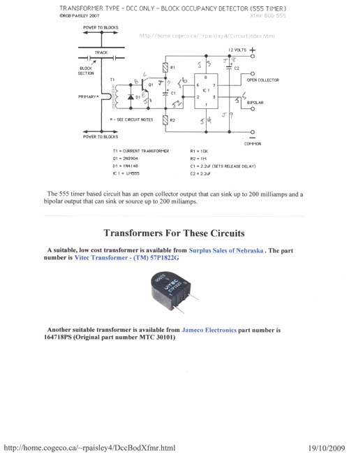
This article falls under the "you can do it too" category. It is not as difficult as one might imagine for the average model railroader, especially with the information available online and articles like this to guide the process....
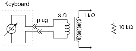
An electronic musical keyboard serves as a source of variable-frequency AC voltage signals. It is not necessary to purchase an expensive keyboard; a model with at least a few dozen voice selections (such as piano, flute, harp, etc.) is...
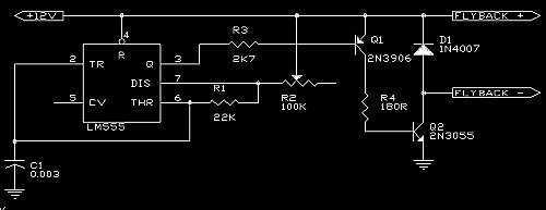
A 555 is used as an oscillator, optimally around 15.76KHz (in North America). Power pins on the chip (pin 1 to ground, pin 8 to +12V) are not shown on the diagram. The output from the 555 is then...
This signal generator is designed for the realignment of radio receivers. It is an economical and straightforward unit, adequate for its intended application. However, the output is not a pure sine wave, which may limit its suitability for more...
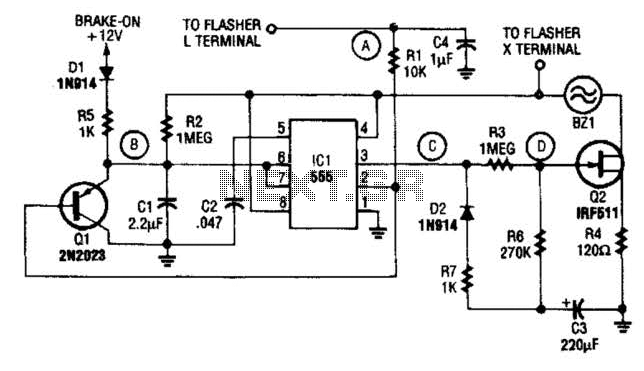
The STS schematic illustrates a circuit designed to alert a driver when the turn signal has been active for more than 15 seconds. The voltage at the gate of transistor Q2 increases in response to the charge accumulated on...
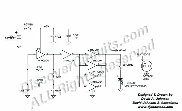
This 40 kHz crystal-controlled oscillator circuit drives an infrared LED with powerful 40 mA pulses. The circuit operates at a frequency of 40 kHz, determined by the crystal oscillator, which provides stable frequency output essential for applications requiring precise timing....