
Servicing the Gottlieb System 1 pinball game
The circuit protection strategy described involves the use of clamping diodes to safeguard sensitive components from voltage spikes. Clamping diodes, such as the 1N4002 or higher, are critical in ensuring that voltage levels do not exceed the specified limits that could damage the IC. By strategically placing these diodes across designated resistors, the circuit can effectively redirect excess voltage away from the IC, thus providing a layer of protection against potential overvoltage scenarios.
The proposed design emphasizes the importance of proper grounding in electronic systems, particularly for the Gottlieb System 1 and 80(X) pinball machines. The modification of the ground connections to the regulator supply enhances the reliability and longevity of the circuit by minimizing the risk of ground-related failures. The incorporation of additional grounding points to the heat sink frame serves to improve the overall electrical stability of the system.
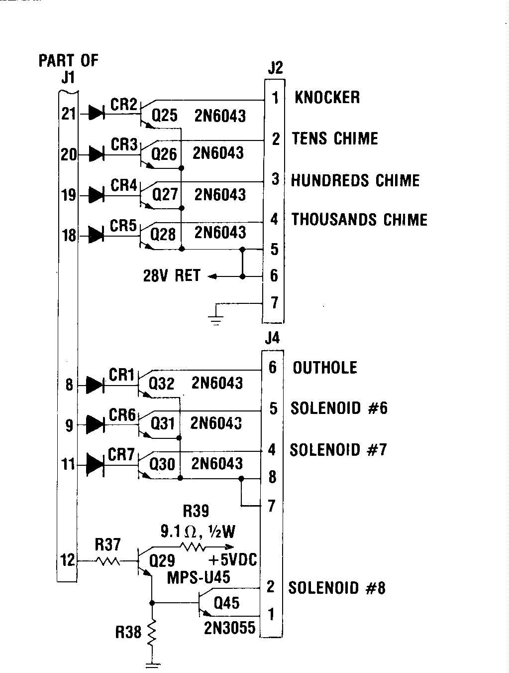
In summary, implementing these modifications not only protects the IC from overvoltage but also addresses grounding issues that may arise from the original design flaws in early Gottlieb pinball machines. This comprehensive approach ensures that the electronic components operate within safe voltage limits and enhances the reliability of the gaming system.A cure that we are testing is to prevent the over voltage getting to the irreplaceable IC U5 - A1752CF after either the switch drives or returns are hit with either a static electric shock or the 24VDC solenoid bus. The protection is simple, there needs to be clamping diodes inserted in the circuit. These can be placed across the resistors R65 - R 72 with the band of the diode (1N4002 or higher) soldered to the +5VDC end of the resistor and the non-band end to the other side of the resistor. Then on Resistors R57 - R62, connect the non-banded end of the diodes (1N4002. ) to the junction of the resistor and the trace leading to the IC and the banded end to a convenient +5VDC bus tie point.
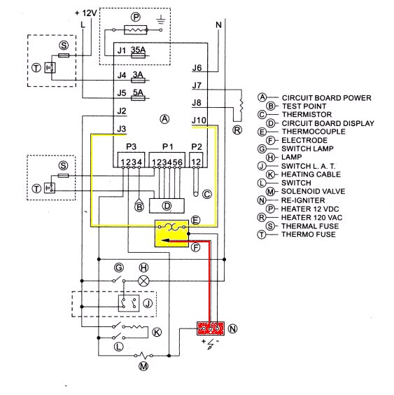
The (-12VDC) is the negative bus rail, and the (+5VDC) is the +5 bus rail. The -|>|- is a diode. The (input/output) is EITHER the input or output line to be protected. This will prevent the input/output lines from going above the +5VDC line and thus protect the IC`s from the 24VDC solenoid bus or the 6. 3VAC light bus power. The earlier run of Gottlieb driver boards did not isolate the MPU board from the solenoid driver transistors, and if a coil shorted out, this can cause serious damage to the MPU board.
Essentially making it very expensive to service! Please check the picture on the lower left (here is a circuit diagram with the diodes) and see if you have these on your board. The early boards can be updated by inserting diodes directly at the base of the driver transistors (picture #2), or traces were cut on the back and the diodes soldered in (picture #3).
The recommended diodes would be 1N4002 to 1N4005 series, Do not use a 1N4001, at 50V it is not rated with a high enough breakdown voltage. We recommend that ALL Gottlieb System 1 game owners confirm this modification has been done, as even though the factory did this modification after the third or fourth pinball in that series, there is always the chance that you do NOT have a modified driver board due to a substitute repaired driver board some time in the past!
Please note that ALL Gottlieb Electronic pinballs have problems with the ground connections. This stems from their refusal to learn from Williams, Bally and Stern`s use of the metal shield as a ground plane for the game boards. Gottlieb System One pins had only a single ground pin going to the regulator supply, and this would weaken over time the same way as the System 80(X) problems are covered below.
A simple cure for the System 1 and 80(X) regulator supply ground problems is to connect the ground plane of the regulator circuit board to one or two of the studs that the securing screws use to hold the circuit board to the regulator`s heat sink, and then making sure that the heat sink frame is connected to the cabinet ground plane. All you need to do is add a wire from the (-) end of the large filter cap to the bolt on the underside of the frame - see the photo.
If you have to take the supply apart for repairs then here is a picture of the mod done to a System 1 power supply (the BLACK wire), also note the fresh heat sink compound (silicon) on the both the outboard +60VDC regulator transistor and the -12VDC regulator. Typically you will turn the game on and the displays will come on IMMEDIATELY. No 5 second delay, no "Click-Click". You might well see the displays showing a wave like this O0O0O0 then 0O0O0O right to left flowing. we recommend that you disable the troublesome/useless SLAM circuit at the MPU board by shorting to ground the junction of R12 and C2.
Finally, please move the battery away from the MPU board. We recommend that you use two extension wires (red and black if possible) and have the battery lying on the bottom of the headboard (in a plastic bag) to protect against battery corrosion. For more info see our battery corrosion page. 7) "Game won`t start Works for a minute or two, then stops Dies when the flippers are flapped Then you might have a pow
🔗 External reference
Related Circuits
This circuit is intended to control a heating system or central heating plan, keeping constant indoor temperature in spite of wide range changes in the outdoor one. Two sensors are needed: one placed outdoors, in order to sense the...
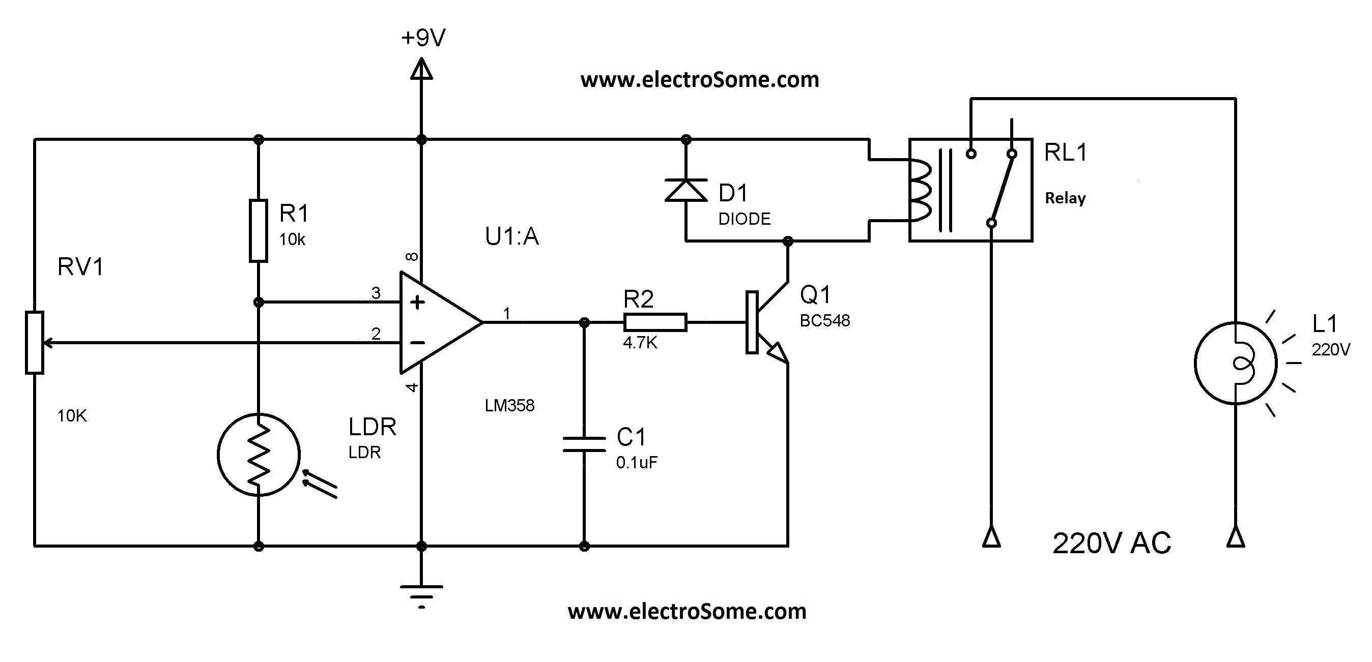
Similar to the previous circuit utilizing the LM358, this design is also cost-effective, priced under 100 rupees. It is a circuit intended for the automatic control of street lights and garden lights. Users do not need to manually turn...
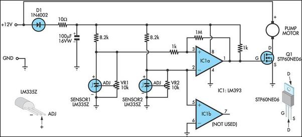
This circuit optimizes the operation of a solar hot water system. When the water in the solar collector is hotter than the storage tank, the pump runs. The circuit comprises two LM335Z temperature sensors, a comparator, and a MOSFET....
With the exception of pilot-type water heaters and some smaller LP/Electric refrigerators, modern LP appliances in RVs are controlled by electronics. Modern LP (liquefied petroleum) appliances utilized in recreational vehicles (RVs) have largely transitioned to electronic control systems, enhancing their...
The anti-theft system includes two frequency sirens connected to the vehicle's immobilizer system. In the laboratory simulation model, the changes in operating modes, siren activation, and fuel supply cut-off are indicated by the illumination of LEDs and communicated to...
.png)
Have you ever considered implementing your own home security alarm system? It is one of the simplest and most interesting circuits for electronics beginners. The new home security equipment utilizes a Light Dependent Resistor (LDR) to detect security breaches....