
Farnsworth Model GT-051 Bakelite Radio (1948)
")
The Bakelite radio set, referred to as "Black Beauty," is characterized by its unique aesthetic and historical significance, representing the Streamline design movement of the 1940s. The restoration process emphasizes maintaining authenticity while addressing functional deficiencies in the electronics.
The radio's circuitry consists of a five-tube AM receiver, which typically includes a combination of radio frequency (RF) amplifiers, a detector, and an audio output stage. The essential components include the 50L6GT audio output tube and the 35Z5GT rectifier tube. The power supply circuit is critical for the operation of the radio, as it provides the necessary voltages for the tubes to function correctly.
In addressing the initial loud hum, the replacement of the filter capacitors is a common and effective first step in restoring functionality to vintage radios. The filter capacitors are responsible for smoothing the rectified voltage and eliminating ripple, which can manifest as audible hum. The use of modern electrolytic capacitors is standard practice, as they offer improved reliability and performance compared to the original paper capacitors that may have degraded over time.
The careful removal of the old filter capacitor, while preserving the metal band attached to the chassis, demonstrates a commitment to maintaining the integrity of the original design. Soldering new components requires attention to detail to ensure that connections are secure and that old leads are completely removed, minimizing the risk of faults due to poor connections.
The persistence of the hum after replacing the filter capacitors indicates that further investigation is necessary. The power resistor, which connects the audio output tube to the rectifier, plays a crucial role in the power supply circuit. If this resistor is compromised, it can lead to unfiltered AC current entering the audio stage, resulting in audible hum. The examination of resistors in the circuit, particularly those that may have drifted in value, is essential for diagnosing the problem.
The audio output transformer also contributes to the overall performance of the radio. Replacing it can resolve issues related to power supply and audio output, especially if the original transformer is suspected to be faulty. The process of measuring voltages at each pin of the tubes will provide valuable data for diagnosing the source of the hum, allowing for a systematic approach to restoring the radio to proper working condition.
Overall, the restoration of "Black Beauty" involves a blend of aesthetic preservation and technical repair, showcasing the importance of both the visual and functional aspects of vintage electronics.Black Beauty" is my nickname for this classy Bakelite set. Sporting a dramatic, assymetrical design, with deep wraparound louvers and a bullet-like profile, it`s a great example of 1940s Streamline design. Definitely a keeper, in other words! I`m restoring the electronics of this radio as well as the cabinet, so let`s look at some highlights of ea
ch process. This radio came from the factory with an ivory paint job. By the time I got my hands on it, though, the paint was deeply chipped in many places. After spending some time trying to smooth out the chipped spots, many of which were on the delicate edges of the louvers, I gave up and removed the paint with a chemical stripper. I don`t normally resort to such drastic measures, but the original paint simply wasn`t salvageable. Before removing the old paint, I brought the cabinet to an auto parts store and found a can of spray paint that looks like a great color match.
When it`s time to repaint, I`ll have exactly what I need. I also carefully masked the bottom to preserve the original paper labels. I first taped a layer of plastic over the labels, using blue "painter`s" masking tape, then covered that layer entirely with a second layer of tape. Stripping the cabinet took a couple of hours. I worked outdoors on our deck, using a brush-on liquid stripper. From aluminum foil, I formed a temporary container about the size of a cakepan to catch the excess stripper and old paint.
Most of the paint brushed off after softening, but a few areas required some careful scraping. For the flattish areas, I used an old putty knife that once belonged to my grandfather. For close crannies and details such as the raised Farnsworth lettering, I used various smaller tools, including toothpicks and a straight pin. Click the thumbnail images to get a closer view of the process. As the paint came off, I was a little surprised to see jet-black Bakelite underneath, rather than the more common brown stuff.
Once stripped, the cabinet required only a little polishing to bring out a nice, even gloss. The cabinet looks so nice in this state that it`s a little hard to think of covering it with paint again! I would probably leave it unpainted forever, but, as you can see, the ivory knobs don`t make a good match with this cabinet color.
I`ll probably leave it this way for a while, but eventually spray on the original ivory color, to make the set more authentic. Inside the distinctive cabinet is a very conventional five-tube AM receiver (see Schematic ). As found, the radio emitted only a loud, low hum, unaffected by either the volume control or the tuner.
It`s working just great now, but the story of how I found the problem is a bit of a twisted tale. Loud hums usually point to problems in the power supply, most often bad filter capacitors, so my first step was to replace the old two-section filter capacitor with two modern electrolytics. That treatment alone will bring many an old hummer back to life. As long as I had the set on the workbench, I replaced all the other old paper capacitors, too. Click on the images below to see the chassis before and after the replacements. Starting with the old filter capacitor, I used a Dremel Moto-Tool to carefully cut the metal band that held it to the chassis.
This allowed easy removal of the old unit without destroying the band, which is riveted to the chassis. Some times this band is mounted with a screw, which makes things a little simpler. The old metal band provided a handy place to route one of the replacements, so I left it in place for that purpose.
Some finicky restorers conceal the new capacitors inside the old paper tubes, making the replacement look more authentic. I have done that on occasion, but these new filters were too big to fit, so I didn`t bother with that nicety.
The radio will work exactly the same, no matter what it looks like under the covers! One area where I do take care, however, is in soldering the replacements. Some times you may see a sloppily repaired set, in which the old capacitor leads were simply snipped off at the case end, and new capacitor leads crudely attached to the old ones. This is a bad idea for several reasons. Most importantly, it relies on an old connection which might be bad. If the old connection was shorted against something, or had a "cold solder" joint, etc. , then your new component will inherit that problem. It`s better practice to remove the old lead completely from the terminal and install the new lead exactly like the original.
This takes more time, since you have to heat the old connection, suck or brush away the excess solder as needed, snip and/or twist the old lead to get it out, crimp on the new lead so that it makes a tight mechanical connection, and finally solder it in place. That sounds harder than it is in practice. After you`ve done it a few times, installing the new component takes only a couple of minutes. The big filter capacitors must be electrolytics, which have a positive and negative end. It`s important to connect electrolytics the right way. If you don`t, they`ll fry and your radio won`t work. The smaller capacitors were replaced with Sprague "orange drops. " Polarity is generally not critical when replacing these guys. The hum still continued after the capacitor treatment, however. When I resumed work the next evening, I double-checked my work to make sure that I hadn`t accidentally reversed polarity on the new filter capacitors or made some other silly mistake.
Seeing nothing obviously amiss, I turned my attention to the GT-051 schematic, which had arrived in that day`s mail. The schematic instantly revealed something that hadn`t been obvious before: the location of the power resistor in the power supply circuit.
It is labeled with number 9 in the schematic, spec`d at 1500 ohms and 1 watt. You will often find the power resistor near the filter capacitors, but in this case it`s buried in the upper right corner of the chassis. You can`t see it at all in the photos, but believe me, folks, it`s there! The power resistor is connected directly from pin 4 of the 50L6GT audio output tube to pin 8 of the 35Z5GT rectifier tube.
If this resistor shorts or loses resistance, it will pass unfiltered AC current into the audio tube. Another potential hum-generator is resistor 8, shown directly below 9 in the schematic. This 10, 000-ohm, 2-watt resistor connects pin 8 of the audio output tube to pin 8 of the rectifier. (In schematics of this vintage, M stands for thousands, not millions. So, the 10 M label by R8 means ten thousand ohms, not ten megohms. Elsewhere on the schematic, you can see MEG used to represent millions. ) I`ll replace both resistors as soon as a fresh supply of spares arrives in the mail. Resistor R9 has a somewhat overheated look, and it is actually a 1400-ohm unit, according to its color coding, not 1500 ohms as specified in the schematic. Perhaps a previous repairman substituted a "close-enough" component because that`s all he had on hand.
In any case, bringing the radio back to spec shouldn`t do any harm. While waiting for my next parts shipment, I`ll double-check the values of all the small capacitors against the schematic. None of their values looked outlandish when I was working, but it never hurts to check. Any tube radio that was used regularly probably had a few paper capacitors replaced in the past, and old-time repairmen were human, just like us.
The next morning, I traded a little mail with Walter Heskes, the designer of this website`s construction projects and an experienced repairman. Looking at the schematic, which I had already posted on the site, he also recommended checking resistor R6, the 470K unit running from pin 5 of the 50L6GT audio tube to the radio`s B- line.
That evening, a check of my capacitor replacements revealed no mistakes, so I resumed the search for the original cause of the hum. With the kids safely tucked in bed, I first made a very close examination of every connection and wire under the chassis.
Perhaps I, or some previous repairman, had accidentally dripped solder somewhere, or nudged a wire out of position so that it shorted against the chassis or another connection. Finding no obvious shorts, I also used my multimeter to check for continuity between a number of connecting points.
Some times a wire may be cracked inside its insulation, so that it doesn`t conduct properly, although it looks fine from the outside. Sloppy soldering can also result in a "cold solder" joint that doesn`t work electronically. This check revealed more good news, of a sort. The radio has many working connections and excellent solder joints. The bad news is that it still hums like crazy! Power resistor R9 was previously tagged as a potential trouble source, so I removed it from the chassis and tested its value with the multimeter.
The reading was 1. 8K, somewhat higher than wanted, but not so far off that it could be causing the hum. Nevertheless, just to eliminate it from the equation, I formed a temporary replacement by soldering two 3. 3K, 1/2-watt resistors in parallel, and putting that back in the circuit. (Wiring two resistors in parallel halves the resistance value and doubles the wattage, so the test unit`s value is 1.
6K at 1 watt. ) Still no change, although I noted that the replacement resistor got very hot when under full power. It wasn`t going up in smoke, but it was hot enough to burn your finger, indicating that it would probably melt down eventually.
The power resistor wasn`t causing the hum, but there`s definitely something haywire in the power supply. I also unsoldered and checked the values of R6, R7, and a few other resistors. One or two had drifted a bit in value, but none had failed to the point where it could cause this gross problem.
The audio output transformer, labeled 23 in the schematic, plays a role in the power supply as well as audio output. These are cheap items, and I had one on hand, so, "out with the bad, in with the good. " Now the radio has a nice, new transformer, but it still hums. You might wonder why I replaced the old transformer instead of simply testing it. Well, by the time you have unsoldered the old leads, it`s approximately the same amount of work to install a new one or reconnect the old one.
I plan to use this radio, not merely display it, so popping in fresh components wherever convenient is not a bad thing to do. And I`ll save the old transformer for a future project or emergency replacement. All right, it`s time to get serious. This evening, I`m going to measure the voltage at every pin of every tube, writing down each value for later comparison against the values given on the schematic.
🔗 External reference
Related Circuits
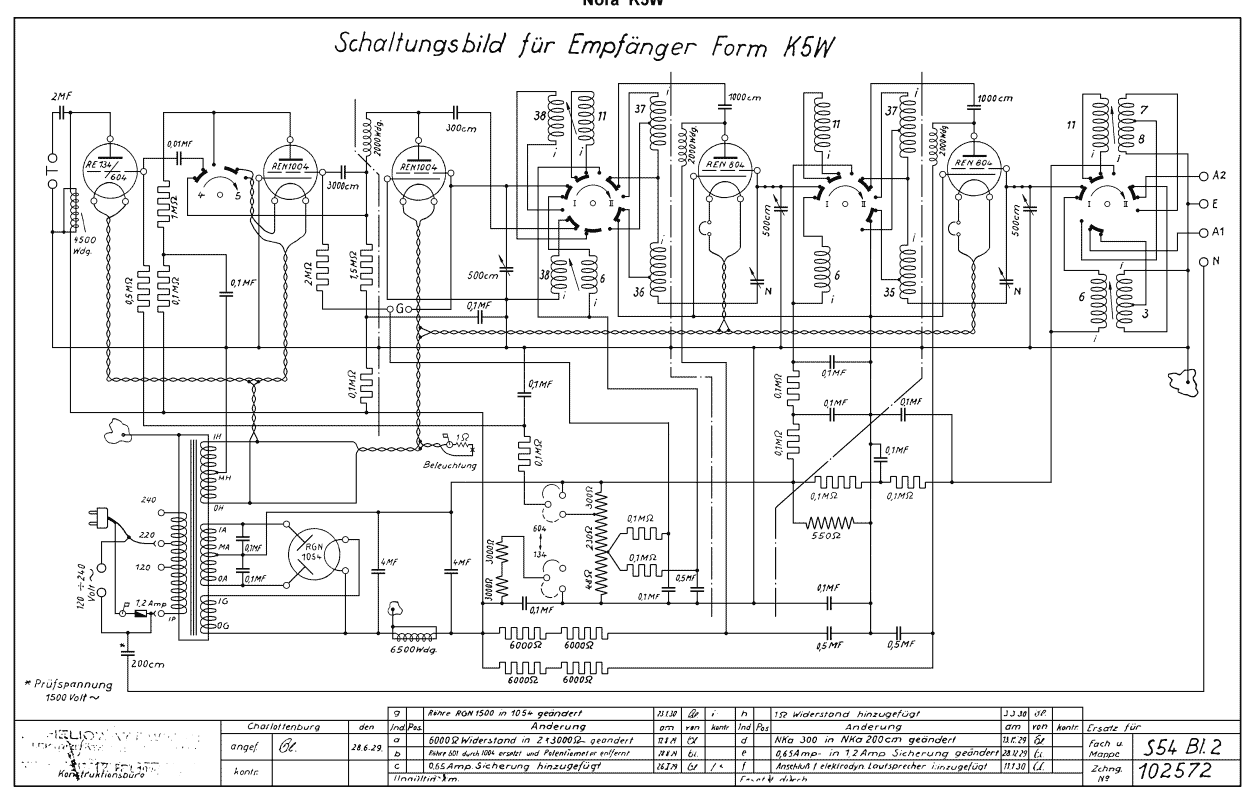
The Nora K5W is a German radio from about 1929/1930. It uses the tubes: 2x REN804, 2x REN1004, RE134 or RE604, RGN1054. The Nora K5W radio receiver represents a significant piece of technology from the late 1920s, showcasing the early...
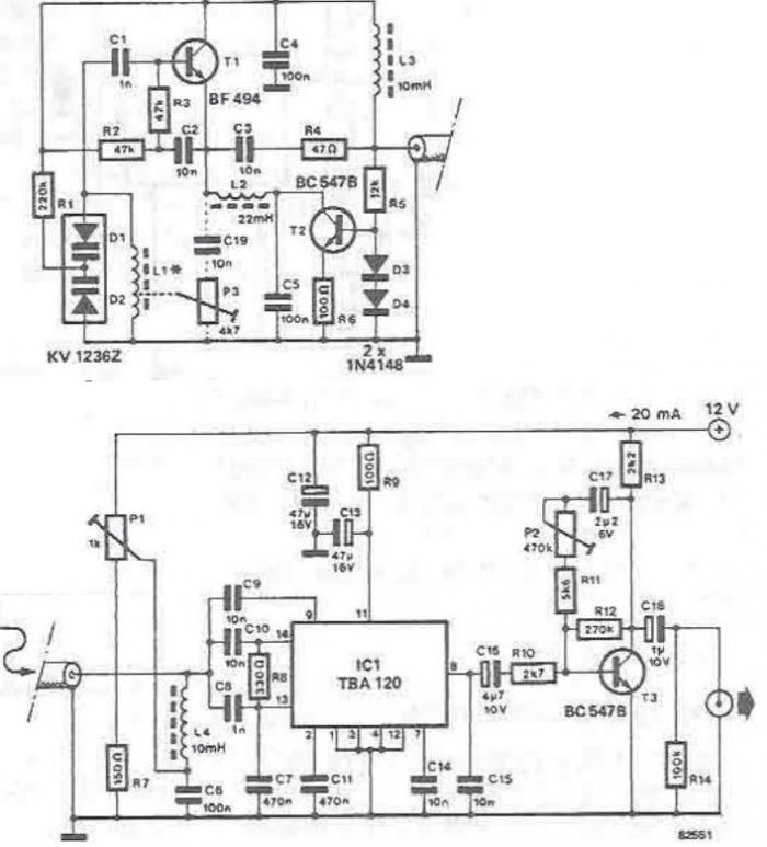
The tuning stage of this long-wave and medium-wave radio receiver also functions as an active antenna, which can be optimally positioned for the best reception. The circuit is completely independent from the receiver, which includes a demodulator that provides...
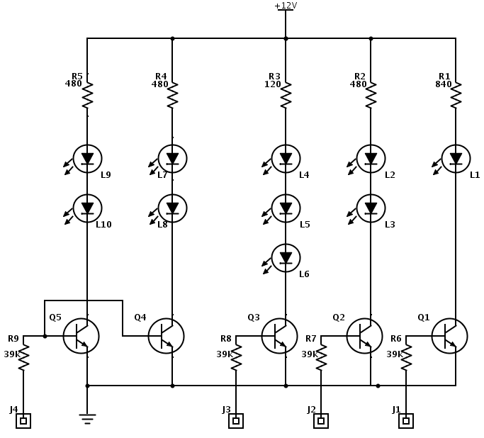
This electronics project involves modifying an old radio into an iPhone dock. Video and pictures are included to illustrate the entire process. The project entails the conversion of a vintage radio device into a functional docking station for an iPhone....
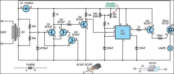
This circuit serves as the foundation for the dimmers in a model theatre lighting system that utilizes touch globes as the light source. It is centered around a 555 timer, which drives a Triac. All dimmers operate from a...
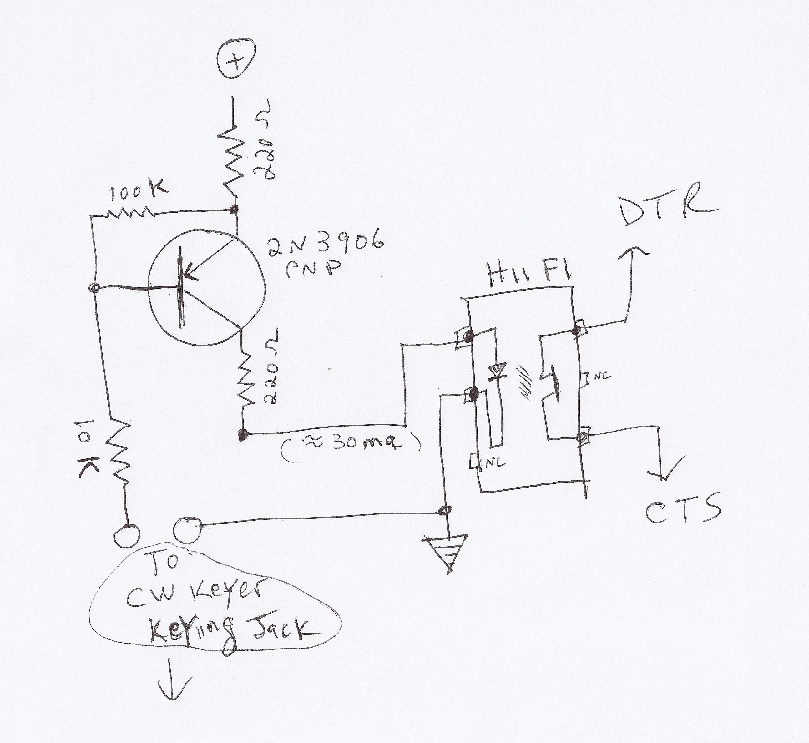
This video demonstrates how to initiate multiple instances of QsoNet's Dahdidah CW Software Keyer using FABULATECH's Virtual Serial Port Splitter. Four separate... The QsoNet Dahdidah CW Software Keyer is a sophisticated tool designed for amateur radio operators, allowing them to...
Small Radio Transmitter. This article contains information about building a small radio transmitter, which has a PCB measuring 1.75 x 2.5 inches (45 mm x 68 mm) and offers a range of approximately 30 yards. The small radio transmitter is...