
Long wave radio and medium wave radio receiver using TBA120
The tuning stage operates by utilizing the properties of the ferrite bar, which enhances the inductance and sensitivity of the tuning coil (L2). The double diode varicap allows for voltage-controlled tuning, enabling adjustments to the resonant frequency of the circuit to match the desired radio frequency. The transistor (T1) serves as a buffer, isolating the tuning stage from the modulator while maintaining a high input impedance, thus minimizing signal loss.
The active antenna configuration is designed to improve reception by amplifying weak signals before they reach the demodulator. The TBA120 modulator integrates the necessary components to process the amplified signal and convert it into audio frequencies. The feedback mechanism ensures stability in the circuit operation, preventing oscillations that could degrade performance.
Coil L1, with its specified number of turns and wire gauge, is critical for achieving the desired resonant characteristics for both long-wave and medium-wave bands. The physical dimensions of the ferrite bar are optimized for these frequencies, ensuring efficient signal capture and amplification. The placement of the feedback loop at a quarter turn from the ground end of the coil is crucial for maintaining the desired phase relationship, which enhances the overall performance of the tuning stage.
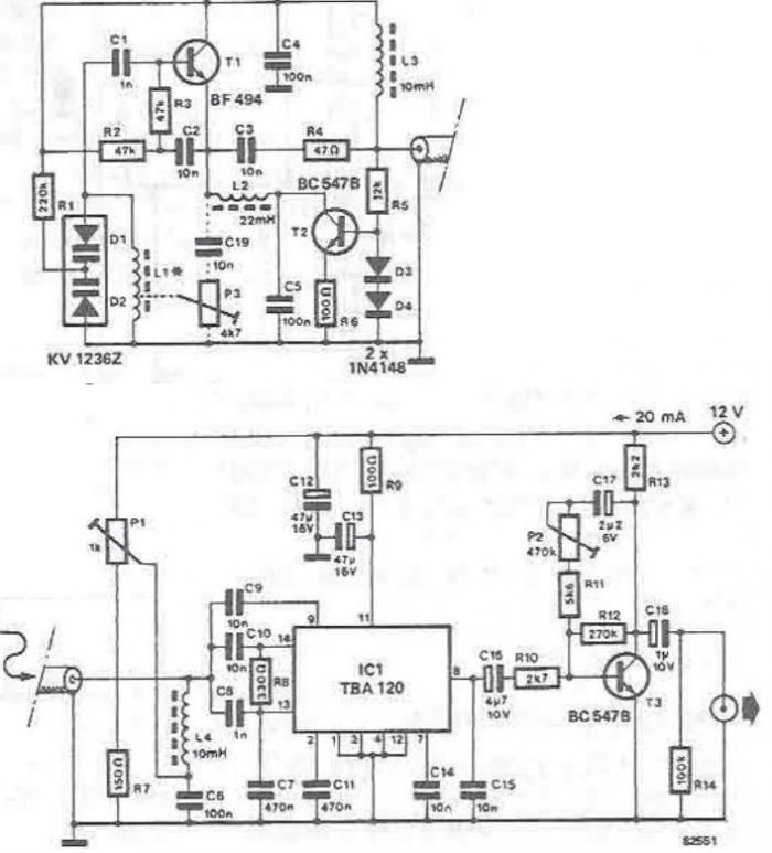
Overall, the described circuit is a sophisticated design that effectively combines an active antenna and a tuning stage, ensuring high-quality reception of long-wave and medium-wave signals. The careful selection of components and their configuration contributes to the circuit's ability to function efficiently in various reception conditions.Tuning stage of this long wave radio and medium wave radio receiver also serves as active antenna that can be favorably positioned to get the best reception possible. Circuit is completely separate from the receiver, which consists of demodulator that provides audio-frequency output.
Plastic case of the antenna input circuit contains a tuning coil designed on a ferrite bar (L2) and a double diode varicap. Antenna signal is transmitted to the tuning stage via a transistor (T1) repeatedly emitter ensuring a high impedance output signal to the modulator. Received signal is amplified by the stage forming active antenna, but a part of the integrated circuit forming TBA120 modulator.
L2 coil emitter serves as a shock to L3 disengages T1 and voltage supply agreement, and thereby prevents shorting the RF output signal of the active antenna. L4 does the same thing for the demodulator. With the exception of L1, coils can be used for standard shocks coils. L1 consists of 250 turns of enamelled copper wire of 0. 2 mm diameter, long-wave range, and 80 turns of enameled copper wire of 0. 3 mm diameter (for medium waves) that is wrapped on a ferrite bar length about 20 cm and a diameter of 10 mm.
Positive feedback loop is connected to an outlet of the coil located at one quarter the number of turns from the end of the ground. 🔗 External reference
Related Circuits
This circuit differs from similar circuits in view of its simplicity and a totally different concept of generating the control signals. Usually remote control circuits make use of infrared light to transmit control signals. Their use is thus limited...
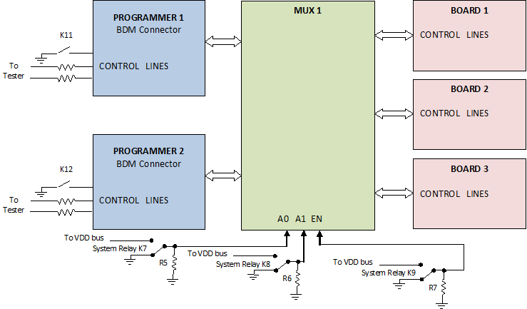
The use of programming pods has become a standard practice in manufacturing, particularly during the early development stages of firmware for new products. Once visual and structural tests are completed, the board is prepared for full functional testing. The...
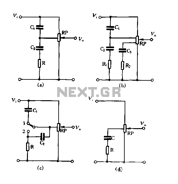
Figure 1.88 illustrates the loudness control circuit utilizing multiple taps on a potentiometer. In Figure (A), the connection is made between the tap and the potentiometer's input, along with the ground. An RC compensation network is employed, where the...
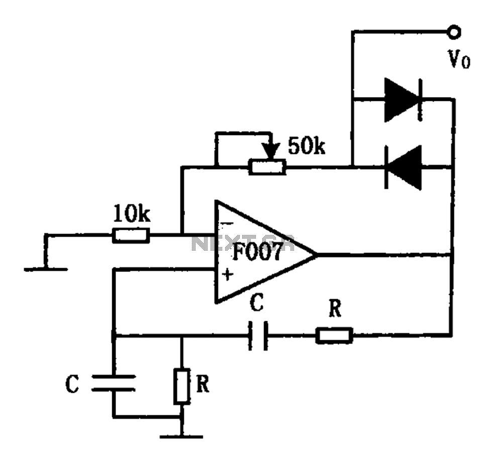
The stable sine wave oscillator circuit is designed to maintain consistent oscillation. The loop gain must be carefully managed; if the gain is excessive, waveform distortion occurs, while insufficient gain can lead to cessation of oscillation. This circuit employs...
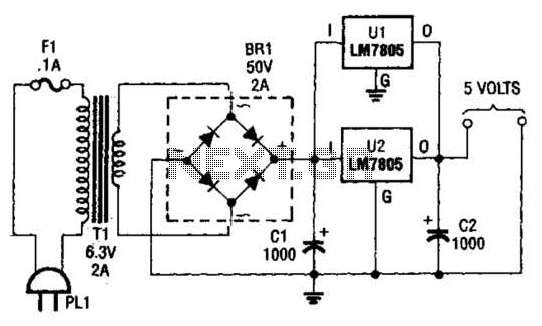
This DC supply is excellent for operating battery-powered antique radios, as it is designed to prevent damage to the tube filaments. The circuit is useful for powering the filaments of 00-A, 01-A, 112A, and 71A tubes, which require 5V...
This is a sine wave oscillator circuit, also known as an amplitude-stabilized sine-wave oscillator. It can provide a high purity sine wave output. The sine wave oscillator circuit is designed to generate a stable and high-quality sine wave output, which...