
Fast Electronic Fuse

The described circuit functions as an overcurrent protection mechanism, utilizing a variable resistor (1k wire-wound potentiometer) to set a threshold for current flow through the load. The potentiometer's wiper position determines the maximum allowable current, and when the load current exceeds this set point, the circuit responds by cutting off the load immediately.
The inclusion of switch S1 allows for two distinct operating ranges. When S1 is open, the circuit is configured to handle lower current loads, specifically in the range of approximately 300-650 mA. In contrast, closing S1 enables a higher current threshold, accommodating loads up to 0.8-2A. This dual-range feature enhances the versatility of the circuit, making it suitable for various applications.
Central to the operation of the circuit is the power resistor or resistors connected in series with the load. These resistors serve a critical role in monitoring the current flow. The voltage drop across these resistors is directly proportional to the load current, following Ohm's Law (V = I × R). When the load current is below the set threshold, the resulting voltage drop across the resistors remains insufficient to activate the transistor T1, which is likely configured as a switch to interrupt the load current.
As the load current increases and approaches the set threshold, the voltage drop across the resistors rises correspondingly. Once this voltage exceeds a certain level, it triggers T1, which then activates a mechanism to cut off the load. This immediate response is crucial for protecting both the load and the power supply from potential damage due to excessive current flow.
Overall, this circuit design effectively combines adjustable current limiting with immediate disconnect functionality, making it a robust solution for overcurrent protection in electronic systems.When the current through the load exceeds a level determined by the position of the wiper on the 1k wire-wound pot, this circuit cuts off the load immediately. If S1 is open, the range is approximately 300-650 mA, and 0.8-2A when it is closed. The key variable in the operation of the fuse is the voltage drop across the power resistor(s) which are connected in series with the load.
This voltage drop is directly proportional to the current the load draws. When this current is low, the voltage across the resistors is also small and cannot trigger T1. 🔗 External reference
Related Circuits

A simple FM transmitter circuit can be designed using the MC2833 integrated circuit, which is intended for cordless telephone and FM communication applications. This circuit includes a microphone amplifier, a voltage-controlled oscillator, and two auxiliary transistors. The final output...
This circuit illustrates a Signal Generator Electronic Circuit Diagram. Features: Unless otherwise specified, resistance values are in ohms. The signal generator circuit is designed to produce various types of electrical signals, which can be sine, square, or triangular waves, depending...
This circuit is derived from information found on electronics websites that focus on IR remote controls. It enables multiple transmitters and receivers to be connected to a common 2-pin bus, which consists of data and ground. The data line...
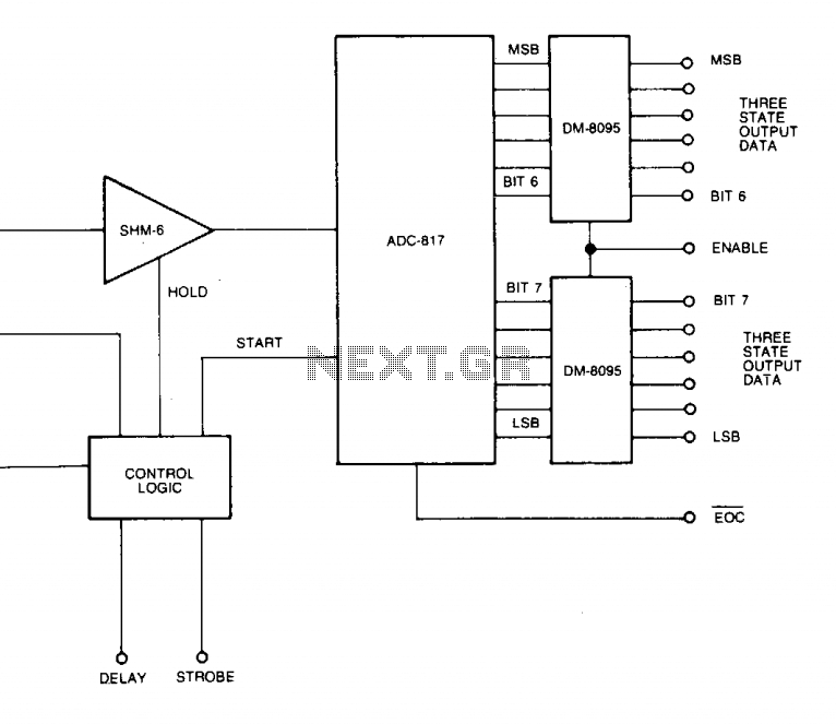
A low-cost, high-speed monolithic analog multiplexer. The system operates by selecting a channel and initiating a conversion at a gain (G) of 1. It then examines the most significant bit (MSB) of the conversion result. If the MSB equals...
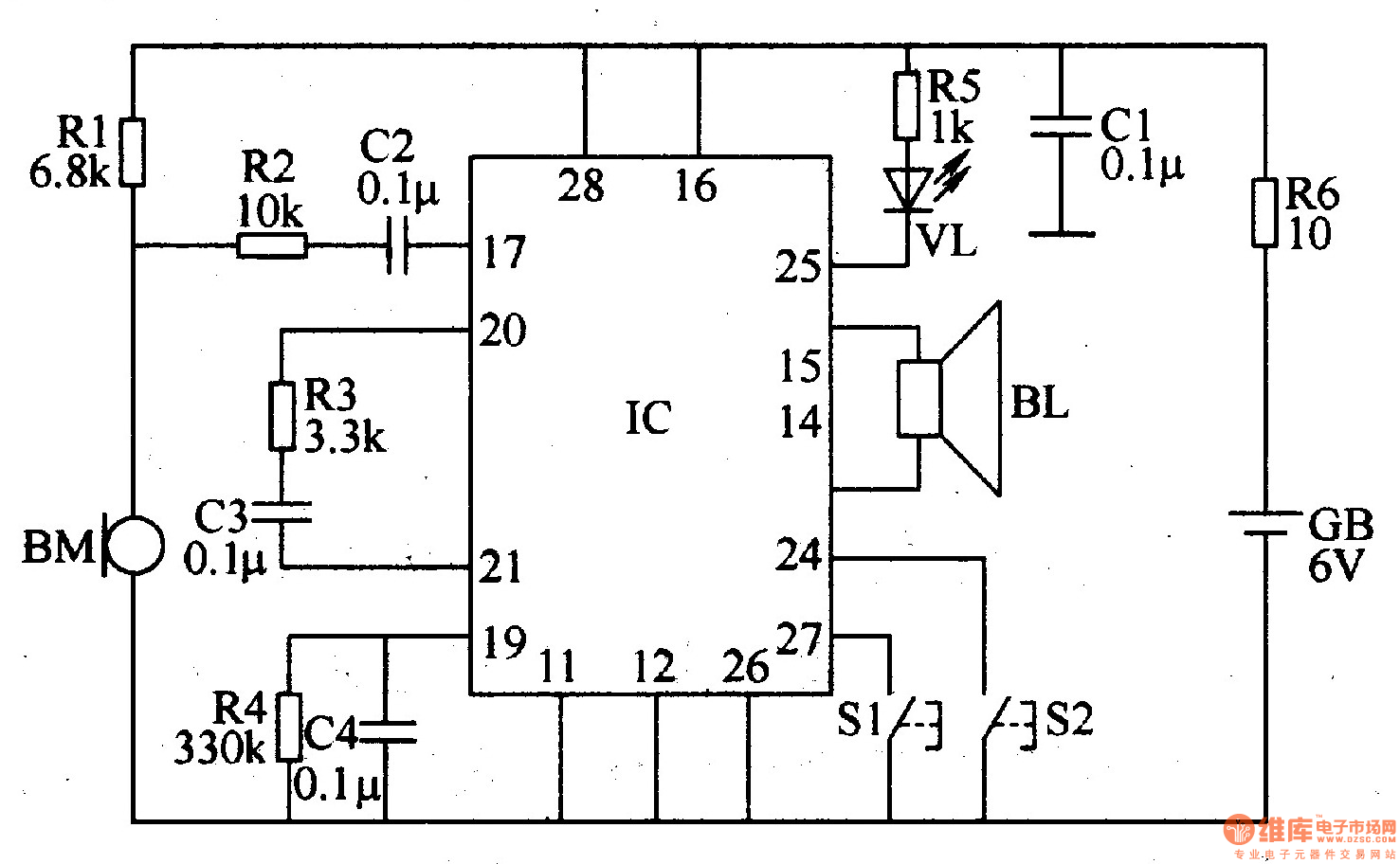
The recordable electronic doorbell consists of a recording and playback integrated circuit (IC), resistors R1-R6, capacitors C1-C4, a microphone (BM), a speaker (BL), control buttons S1 and S2, a battery (GB), and an LED (VL). Resistors R1-R5 should be...
Life in the 21st century would be almost unbearable without some of the computer peripherals that PC users now look upon as essentials, such as keyboards, mice, and printers. Computer peripherals play a crucial role in enhancing the functionality and...