
Signal Generator Electronic
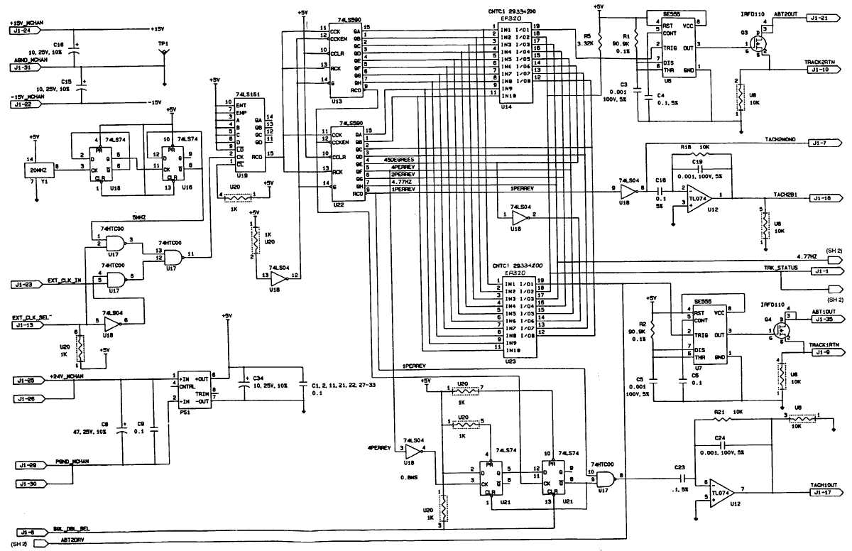
The signal generator circuit is designed to produce various types of electrical signals, which can be sine, square, or triangular waves, depending on the configuration of the components used. Typically, this circuit includes a function generator IC, such as the 555 timer or a dedicated waveform generator IC, along with passive components like resistors and capacitors that determine the frequency and amplitude of the output signal.
In the case of a 555 timer configured in astable mode, it generates a square wave output. The frequency of the output can be calculated using the formula:
\[ f = \frac{1.44}{(R1 + 2R2)C} \]
where \( R1 \) and \( R2 \) are the resistances connected to the timing capacitor \( C \). The duty cycle, which defines the proportion of time the signal is high versus low, can be adjusted by varying the values of \( R1 \) and \( R2 \).
For sinusoidal output, a more complex arrangement may be needed, often using operational amplifiers to shape the waveform appropriately. The circuit may also include a low-pass filter to smooth out the output signal, ensuring that it closely resembles a sine wave.
The output of the signal generator can be connected to various loads or circuits for testing and experimentation purposes. Proper consideration should be given to the output impedance and the load characteristics to ensure signal integrity. Additionally, power supply requirements should be clearly defined, as they can affect the performance and stability of the generated signals.
Overall, this signal generator circuit is a versatile tool in electronics, suitable for various applications including testing, signal modulation, and waveform analysis.This circuit shows about Signal Generator Electronic Circuit Diagram. Features: UNLESS OTHERWISE SPECIFIED, RESISTANCE VALUES ARE IN OHMS, .. 🔗 External reference
Related Circuits
The temperature measuring range of this electronic thermometer is 0-50 degrees Celsius, with a precision of 0.1 degrees Celsius. The measurement results are intuitively displayed on a digital screen. This electronic thermometer circuit consists of a temperature detection circuit,...
For the past year and a half, a group based in Ann Arbor, Michigan, named GO-Tech has been formed, uniting individuals interested in creating projects using technology, such as hardware, software, metal, and wood. This initiative is referred to...
The objective of this project is to prevent vehicle collisions by utilizing an ultrasonic anti-collision device. This device is mounted on the front of the vehicle and detects nearby vehicles or obstacles. The ultrasonic anti-collision system operates by emitting ultrasonic...
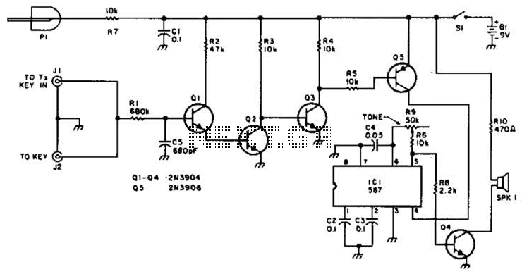
For use with low-power transmitters that require a positive keying voltage. The transistors Q1, Q2, and Q3 are configured as a switching amplifier. When the key is pressed, the collector of Q3 is pulled to ground, which activates Q5...
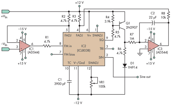
This basic voltage-controlled oscillator (VCO) and waveform generator integrated circuit (IC) circuit features a voltage follower loop (formed with IC1) and a symmetry feedback loop (IC3) designed to eliminate asymmetric duty cycles that can lead to distortion at low...
A platform for sharing and discovering articles and documents. Users can upload their knowledge, share it with others, or search through the database to find relevant articles. This platform serves as a collaborative space where individuals can contribute their expertise...
Warning: include(partials/cookie-banner.php): Failed to open stream: Permission denied in /var/www/html/nextgr/view-circuit.php on line 713
Warning: include(): Failed opening 'partials/cookie-banner.php' for inclusion (include_path='.:/usr/share/php') in /var/www/html/nextgr/view-circuit.php on line 713