
Fast Voltage-Driven Current Source
The current source depicted in the schematic is designed to provide a stable output current that responds rapidly to variations in the input signal. This characteristic is particularly beneficial in applications requiring precise measurements, such as in differential measurement systems. The ability to react swiftly to input changes ensures that the current source can accurately track dynamic signals, minimizing lag and improving measurement fidelity.
In a typical configuration, the current source may utilize operational amplifiers to regulate the output current. The feedback mechanism employed in the design allows for quick adjustments in response to fluctuations in the input signal, thus maintaining a consistent current output. The differential nature of the current source can be advantageous in reducing common-mode noise, enhancing the overall signal integrity during measurement operations.
Furthermore, the current source may be integrated into various electronic systems, such as analog-to-digital converters (ADCs) or sensor interfaces, where rapid response times are critical. The design should also consider factors such as temperature stability and power supply variations, ensuring reliable performance across a range of operating conditions. Overall, the current source serves as a vital component in high-precision measurement applications, contributing to improved accuracy and reliability.The current source in the diagram, which react very fast to changes in the input signal, may be used, for instance, in certain measurements. Differential.. 🔗 External reference
Related Circuits
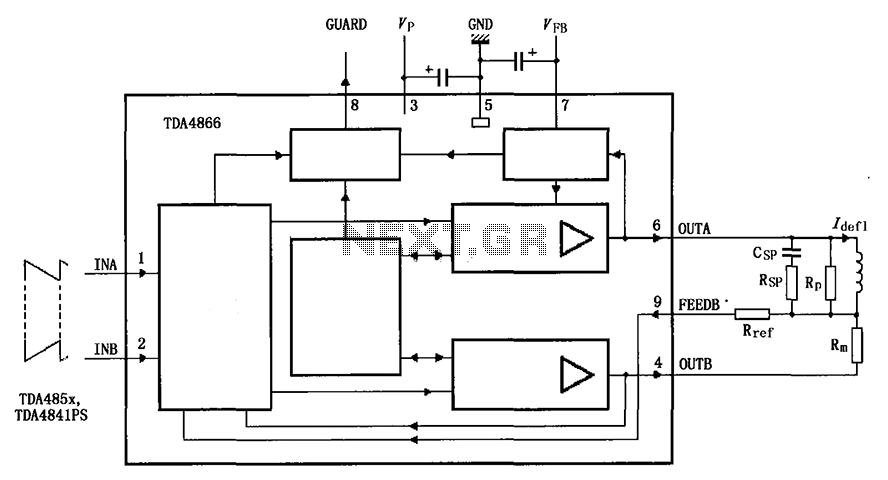
The TDA4866 is a 90-color power amplifier designed for vertical deflection systems, operating at a frequency range of 50 to 160 Hz. The CRMM circuit is implemented to ensure a high current drive input. The amplifier features a dual...
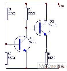
When the current is below the specified threshold, the bias current supplied by resistor R1 causes transistor P3 to saturate and conduct. In this state, it is unable to regulate the current effectively. Conversely, when the current reaches or...
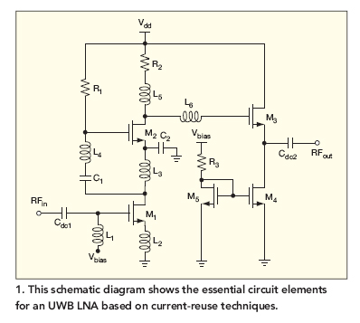
This broadband low-noise CMOS amplifier operates within the ultrawideband (UWB) communications frequency range of 3.1 to 10.6 GHz, utilizing current-reuse techniques. The broadband low-noise CMOS amplifier is designed to enhance signal integrity and minimize noise within the specified UWB frequency...
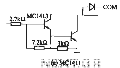
The MC1411 series is a Darlington driver with a compact, reliable internal structure. It is particularly suited for high-voltage applications, functioning effectively as a high-voltage peripheral driver. This driver can directly control relays, lights, and other loads. It is...
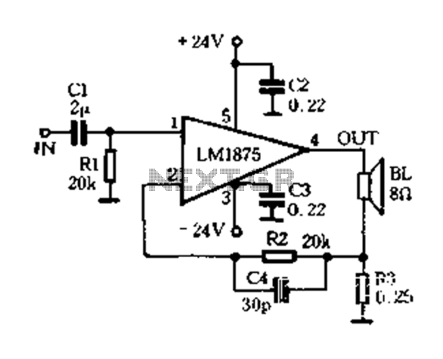
A current-sense amplifier is utilized to enhance the performance of the LM1875 current-mode amplifier circuit, as depicted in Figure 5-20. The resistor R3 and the series resistance of the speaker contribute to the current flowing through R3. This current...
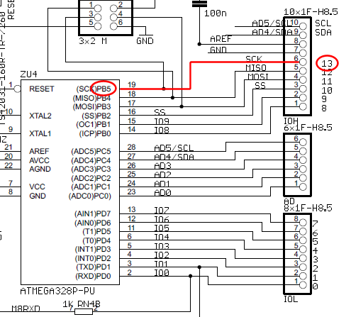
The wire connected to the 5V pin is linked to the positive pins of the breadboard, which are not connected to any other components. There are no additional connections on the positive column. While this may seem like a...
Warning: include(partials/cookie-banner.php): Failed to open stream: Permission denied in /var/www/html/nextgr/view-circuit.php on line 713
Warning: include(): Failed opening 'partials/cookie-banner.php' for inclusion (include_path='.:/usr/share/php') in /var/www/html/nextgr/view-circuit.php on line 713