
Simple current limiting circuit

In this circuit configuration, the primary function of resistor R1 is to set the bias current for transistor P3, ensuring that it operates in the saturation region when the input current is below the defined threshold. The saturation of P3 allows it to conduct fully, but this state does not provide current regulation, leading to potential overcurrent conditions. Resistor R serves as a sensing element; it monitors the current flowing through the circuit. As the current increases, the voltage drop across R rises, eventually reaching a point where it closely matches the voltage drop across R2. This alignment is critical for the regulation process.
When the current exceeds the set threshold, the circuit's operation transitions to a limiting mode, where the increased voltage drop across R restricts the current flowing through P3. This mechanism effectively prevents the current from rising beyond a predetermined level, protecting downstream components from damage due to excessive current. The incorporation of resistor R2 as a regulator enhances the precision of this current limiting feature. By providing a more stable reference for the voltage drop, R2 can help fine-tune the performance of the circuit, resulting in improved accuracy in current regulation.
However, it is important to acknowledge the limitations of this protection mechanism. During overload scenarios, such as a short circuit, the majority of the voltage drop may occur across the transistor. This situation can lead to increased power dissipation, which can adversely affect the thermal performance and reliability of the circuit. Careful thermal management and component selection are essential to mitigate these risks and ensure the circuit operates within safe limits under all conditions. Overall, this circuit design emphasizes the balance between effective current regulation and the inherent trade-offs associated with power dissipation during fault conditions.When the current is less than the value set, the bias current provided by R1 leads the P3 to be saturated to conduct. And it can not afford to control the current. When the current is greater than or equal to the set value, the pressure drop on R would increase and be close to the pressure drop of R2 after acrossing the transistor junction.
Then i t can limit the current through P3 in order to limit the current to a certain level. If R2 is used as a regulator instead, the limiting performance can be more accurate. The drawback of the introduced protection circuit is that the pressure drop can be all down on the transistor when the current is overload, especially a short circuit. Thus, it would lead to certain power consumption. 🔗 External reference
Related Circuits
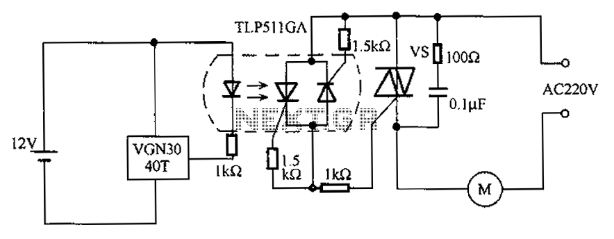
The circuit utilizes an integrated Hall effect sensor for an AC motor control system. It operates by detecting the presence of magnets or other magnetic objects near the Hall IC element of the induction motor. This configuration functions as...
A high voltage power supply is a valuable source that can be effectively used in various applications, such as biasing gas-discharge tubes and radiation detectors. This type of power supply can also serve as a protective measure, such as...
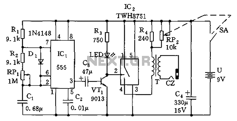
The circuit is composed of a 555 oscillator and an amplifier driver stage. It includes the 555 timer along with resistors R1, R2, RP1, capacitor C1, and other components forming a multi-harmonic oscillator. The frequency can be adjusted using...
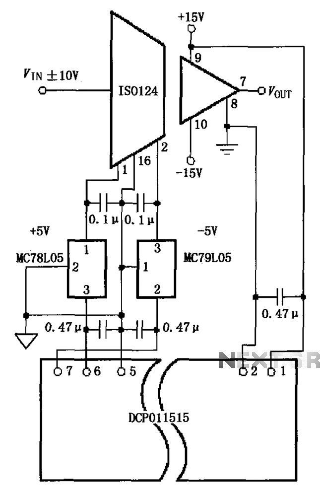
The circuit depicted in the figure includes the ISO124 and MC78L05 components, along with an external regulator, MC79L05, and the DCP011515, which collectively enhance the power supply rejection ratio (PSR) of the circuit. The input signal, VIN (maximum swing...
The electronic components designed by conventional electronic bonsai create a sparkling and brilliant atmosphere in the living room, enhancing the joys and pleasures of life. The selection of components includes IC1 to IC4, which consist of two pairs of...
The circuit is designed for high precision operation over an extended temperature range, provided that V+ remains relatively constant, as the current IZ is dependent on V+. Resistors R1, R2, R3, and R4 are selected to ensure the appropriate...