
faster charger circuit 6-12 volt

This rapid battery charger circuit utilizes integrated circuits LM308 and LM317, which are well-regarded for their voltage regulation capabilities. The circuit is structured to accept a 15V DC input, which is then processed to deliver a variable output voltage between 6V and 12V, allowing for compatibility with various battery types. The adjustment of the output voltage is facilitated by the component D1, which should be configured to maintain a voltage differential of 50 mV above the Zener voltage of D2. This precise setting is crucial for ensuring that the charging process is efficient and prevents overcharging.
The LM317 serves as a voltage regulator in this configuration, providing a stable output voltage that can be fine-tuned for the specific battery being charged. The inclusion of the LM308 allows for additional control over the circuit's performance, especially in terms of temperature management, as it helps prevent overheating during operation. The design ensures that the charger operates at a low temperature of 5 degrees Celsius, which is beneficial for maintaining battery health and longevity.
Connection to the battery is established through D2, which is directly coupled to the battery terminals. This setup allows for effective charging of both 6V and 12V batteries, accommodating different battery chemistries, including lead-acid (dry and wet) batteries. The versatility of this circuit makes it suitable for various applications where rapid battery charging is desired. Proper implementation of this circuit will yield efficient charging times while maintaining safe operational parameters.This circuit is quickly charging the battery. If you need a faster charger, this circuit is recomended to you. And this charger is low temperature, the temperatur is 5 degree celcius. Input Voltage is 15 Volt DC, and Output voltage to charging 6 -12V and you can adjust by the D1 (see schematic). And adjust the D1 to 50 mV greater VZ than D2 (s ee schematic). Couple the D2 to battery. This circuit operating by IC LM308 and LM317 and any other components. And you can use this circuit to charging Accu 6 or 12 Volt, dry or wet and other battery. You are reading the Circuits of Faster Battery Charger Circuit 6-12 Volt with IC LM308 and LM317 And this circuit permalink url it is 🔗 External reference
Related Circuits
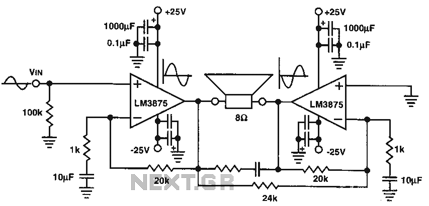
The audio power amplifier delivers 80W of audio power to an 8-ohm load. The LM3875 integrated circuit (IC) requires adequate cooling. It is important to note that in the bridge amplifier configuration, the two connected speakers will produce heat. The...
There are many circuits for low voltage regulators. For higher voltages, such as supplies for valve circuits, the situation is different. Low voltage regulators are widely utilized in electronic circuits to provide a stable output voltage from a varying input...
This multimeter is designed to measure output voltage and current in a power supply unit (PSU), with the current sense shunt resistor connected in series with the load at the negative voltage rail. It operates using a single supply...

This design outlines a simple wideband output amplifier suitable for use as a 50-ohm transmission line driver. The circuit is constructed using the CA3140 operational amplifier. When utilized alongside the function generator and sine wave shaper circuits, it delivers...
A recent thrift shopping experience revealed a toy that appears to be suitable for circuit bending. The toy was found without batteries, preventing any testing at the store. It may be beneficial to bring batteries during future visits or...
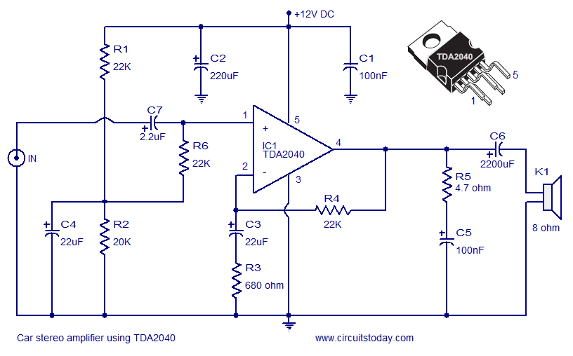
A car stereo amplifier circuit utilizing the TDA2040 is presented here. The TDA2040 is a monolithic integrated audio amplifier that functions in Class AB mode. This integrated circuit features built-in short circuit protection and thermal shutdown capabilities, and it...