
High-Voltage Regulator With Short Circuit Protection

Low voltage regulators are widely utilized in electronic circuits to provide a stable output voltage from a varying input voltage source. These regulators are essential in applications where precise voltage levels are critical for the operation of sensitive components. Common low voltage regulator circuits include linear voltage regulators (such as the LM7805 for +5V output) and switching voltage regulators, which can efficiently step down or step up voltage levels.
In contrast, high voltage applications, such as those involving valve circuits, present unique challenges. Valve circuits often require higher voltages for operation, which necessitates the use of specialized high voltage regulator circuits. These circuits must be designed to handle higher voltage levels safely while maintaining regulation accuracy and efficiency.
High voltage regulators may utilize components such as high voltage transistors, Zener diodes, or specialized integrated circuits designed for high voltage applications. The design considerations for these circuits include thermal management, component ratings, and safety measures to prevent overvoltage conditions. Additionally, filtering components may be required to eliminate noise and ensure stable operation in high voltage environments.
When designing a high voltage regulator circuit, it is crucial to consider the load requirements, input voltage range, and desired output voltage. Proper selection of components and circuit topology will ensure reliability and performance in applications where higher voltages are essential.There are many circuits for low voltage regulators. For higher voltages, such as supplies for valve circuits, the situation is different. That s why we de.. 🔗 External reference
Related Circuits
The buba oscillator initially failed to oscillate. The first step is to check the fundamental components, as minor errors in the values of capacitors, resistors, and inductors can significantly impact performance. It is advisable to measure component values with...
Hello everyone, I am not well-versed in electronics, so I would appreciate it if someone could create a diagram for me. I would like to modify a circuit so that it can dial a number using speed dial and...
This page shows some methods of track routing control for Stall-Motor type switch machines. The principle method uses a 2 Pole - Multi Position rotary switch while an alternate uses optoisolators and transistors to select the routes. The last...
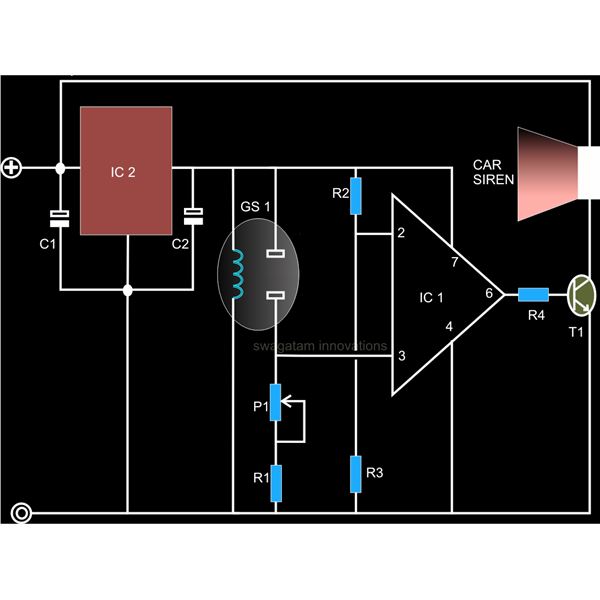
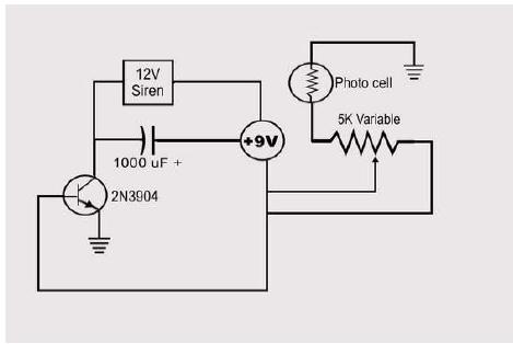
A straightforward smoke detector circuit has been presented through a schematic diagram, which can be easily constructed and installed in an area for essential detection purposes. The circuit utilizes the versatile FIGARO TGS 813 gas sensor as the primary...
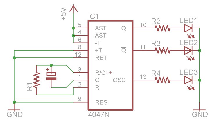
The oscillator output generates a signal that is approximately twice the frequency of Q. The other pins will be considered subsequently. In a brief video demonstration, LEDs are connected to all three outputs, illustrating the alternating behavior of Q...
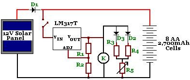
The circuit is designed to power a CCTV camera, provide lighting inside a nestbox, and charge batteries using a photovoltaic (PV) solar panel. It includes a circuit diagram for a solar-powered wireless CCTV camera with battery backup. D1 is...