
Fastest Finger First Indicator
The circuit design for the quiz-type game show incorporates several integrated circuits (ICs) to create a robust and efficient system for determining the fastest contestant. The core functionality is based around the latch IC (7475), which captures the state of the contestant buttons. When a button is pressed, the corresponding latch output changes, signaling which contestant has responded first.
The dual 4-input NAND gates (IC3, 7420) serve a critical role in ensuring that once a contestant has been registered, the system locks out any further inputs. This is accomplished by generating a latch-disable signal that prevents any additional button presses from being recognized, thus maintaining the integrity of the game.
The priority encoder (IC4, 74147) translates the active-low signals from the latches into a BCD output, which is essential for displaying the contestant number on the LED display. The inverter gates within the hex inverter IC (74LS04, IC5) ensure that the signals are correctly formatted for the BCD-to-7-segment decoder (IC6, 7447), which drives the common-anode LED display. This display shows the contestant number in a clear and visible format for both the audience and the game host.
The audio alarm system, utilizing the 555 timer IC (IC7), is designed to provide an audible cue when a contestant presses their button. The frequency of the alarm can be adjusted by the preset resistor (VR1), allowing for customization based on the environment or audience size. The 12V power supply for the audio system ensures that the alarm is loud enough to be heard clearly.
The entire circuit is powered by a regulated 5V supply, created by the voltage regulator IC (IC1, 7805), ensuring stable operation of the logic components. The reset function, activated by pushbutton S5, allows the game organizer to clear the display and silence the alarm once a contestant has been identified, preparing the system for the next round.
This design can be expanded to accommodate more than four contestants with minor modifications, making it versatile for various game show formats. Overall, the circuit effectively combines logic control, display management, and audio signaling to create an engaging and competitive game show environment.Quiz-type game shows are increasingly becoming popular on television these days. In such games, fastest finger first indicators (FFFIs) are used to test the player`s reaction time. The player`s designated number is displayed with an audio alarm when the player presses his entry button. The circuit presented here determines as to which of the four contestants first pressed the button and locks out the remaining three entries. Simultaneously, an audio alarm and the correct decimal number display of the corresponding contestant are activated. When a contestant presses his switch, the corresponding output of latch IC2 (7475) changes its logic state from 1 to 0.
The combinational circuitry comprising dual 4-input NAND gates of IC3 (7420) locks out subsequent entries by producing the appropriate latch-disable signal. Priority encoder IC4 (74147) encodes the active-low input condition into the corresponding binary coded decimal (BCD) number output.
The outputs of IC4 after inversion by inverter gates inside hex inverter 74LS04 (IC5) are coupled to BCD-to-7-segment decoder/display driver IC6 (7447). The output of IC6 drives common-anode 7-segment LED display (DIS. 1, FND507 or LT542). The audio alarm generator comprises clock oscillator IC7 (555), whose output drives a loudspeaker. The oscillator frequency can be varied with the help of preset VR1. Logic 0 state at one of the outputs of IC2 produces logic 1 input condition at pin 4 of IC7, thereby enabling the audio oscillator.
IC7 needs +12V DC supply for sufficient alarm level. The remaining circuit operates on regulated +5V DC supply, which is obtained using IC1 (7805). Once the organiser identifies the contestant who pressed the switch first, he disables the audio alarm and at the same time forces the digital display to 0` by pressing reset pushbutton S5. With a slight modification, this circuit can accommodate more than four contestants. 🔗 External reference
Related Circuits

The automatic alarm circuit comprises a DTMF automatic dialing system, a password control circuit, a voice detection and alarm circuit, a telephone interface circuit, a power supply circuit, and a keyboard display circuit. The automatic dial-up alarm utilizes the...
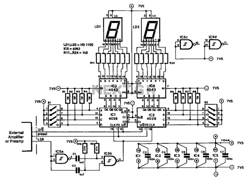
The indicator is designed for use with an audio amplifier or preamplifier, but it can also be utilized in other applications requiring rapid counting of steps or changes. To avoid interference with the audio signal, the circuit operates in...
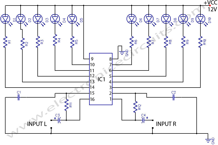
LED stereo sound level indicator for audio amplifier. Many circuits can be designed as level indicators by using a comparator IC or transistors, but... The LED stereo sound level indicator serves as a visual representation of the audio signal levels...
It is sometimes necessary to monitor a device that generates a relatively short pulse to indicate a change of status. If the duration of the input signal is too short, the RFC-1/B may not have enough time to capture...
Following a highly successful Kickstarter project and over a year of development, HexBright, described by its creator as the world's first open-source Arduino flashlight, is now in production with initial shipments planned for December. HexBright, which was discussed in...

12V Battery Charge Nominal Discharge (Low) Indicator Circuit. This circuit monitors car battery voltage and provides an indication of nominal supply voltage, as well as low or high voltage. The 12V Battery Charge Nominal Discharge Indicator Circuit is designed to...